


HARSFEN0602
14.9 Diagnosis
14.9.1 Monitoring motion faults
You can monitor motion faults by:
Continuously polling the amplifier status
Observing an "AOK" digital outputs.
Trapping CAN Emergency objects. The CAN Emergency objects are covered in the
CAN manual.
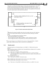
14.9.1.1 Polling the amplifier status
The amplifier can be polled using the SR command. The SR command reports a bit-field
that draws an entire picture of the amplifier activity. One of the bits of SR (refer the
Command Reference Manual) reports the existence of motion fault.
Another bit of SR reports the existence of a user program fault.
When a motor fault is detected, the MF command will report the exact reason for that fault –
refer the Command Reference Manual.
When a program fault is detected, the PS command will report the fault reason.
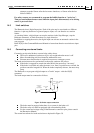
14.9.1.2 Observing AOK
One of the digital outputs may be programmed to reflect that the amplifier is ready – no
physical reason such as over-temperature, over voltage, or under voltage prevents the
amplifier from working. The AOK output reports that physical operation conditions exist,
but it tells nothing about the motion status.
14.9.2 Inconsistent setup data
The setup data is checked when loading the setup from the parameters non-volatile flash storage, and
before starting the motor.
When the setup parameters are retrieved from flash storage (At power-on, or by an LD command),
they are thoroughly checked for legality and consistency. If the parameters are found illegal or
inconsistent, the amplifiers resets to its factory defaults. What was wrong can be found using the CD
command (see below), and the contents of the flash storage can be corrected using the application
editor.
Loading the setup parameters from the flash will rarely fail, since the parameters are checked before
allowing non-volatile storage. The almost only failure reason is a major firmware revision upgrade.
Before enabling the motor, the Amplifier tests that all of its parameters make sense.
For example, the variables CA[4], CA[5], and CA[6] define how the Hall sensors are ordered. If CA[4]
equals CA[5], then two Hall sensors are assigned to the same position, which is an absurd (refer the chapter
"Commutation").
With CA[4]=CA[5], the command MO=1 will fail and return the error code of 54, meaning “Bad database”.
In order to find the reason for the “bad database” failure, use the CD command. The CD command will
return
Null Address=0
Failure address=0
Called Handler=none
Database Status:
CA[4], error code=37
The first lines establish that the CPU detected no exception (refer "Device failures, and the CPU dump"
below).
The last line states that the parameter CA[4] yielded the error code 37, meaning "Two Hall sensors are
defined to the same place" – please refer the EC command in the Command Reference Manual.
Other exceptions that may be caught at motor on are: