


HARSFEN0602
of PY, not PX.
13.5.4 On the fly position counter updates
The updating of a position sensor during homing process has no effect in UM=1,2,3 since
these modes do not use position feedback.
The implications of position sensor (PY in UM=4, PX in UM=5) update by a homing
process depend in the mode.
In PTP motions, the remaining motion to target becomes longer or shorter – refer
example below. If the home correction is made in a constant speed region of the
PTP motion, the redesign of the motion path may be hardly visible. This mechanism
enables registration and final motion corrections on the fly.
In Jog motions, the position command is jumped according to the position feedback,
so that the motion is unaffected by the position counter update.
If the software position reference generator is stopping or stopped, the software
position command is corrected according to the position feedback. The motion is
unaffected by the position counter update.
In PVT or PT motions, an on-the-fly position counter update may lead to immediate
high position error, and the motor may abort with an excessive position tracking
error exception.
If with UM=5 the auxiliary encoder counter is modified, and the following is true:
The motor tracks the auxiliary encoder with no ECAM table (RM=1, FR[3]
nonzero, EM[1]=0).
The software position generator is Idle, Jogging, or running PTP
The software position reference is modified so that the motion shall not be affected. In the
PTP mode, the parameter PA will change automatically to reflect the modification.
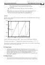
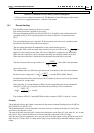
Example:
A PTP motion starts with PA=PX=0. We set PA=1000;BG;, and expect an 1000 counts long
motion. If, at PX=500, the position has been reset to zero by homing, then immediately after
the homing we still have 1000 counts to go. The total length of the motion becomes 1500.
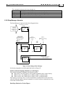
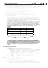
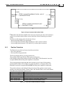
13.5.5 A homing with home switch and index example
Consider the very common switch arrangement of Figure 35.
A homing algorithm may be:
Start the motor
Jog back until RLS.
Jog forward speed until home.
Look for the next index and set the position there to 0.
The position setting is taken by the index, since in many applications the index is much
more accurate then the home switch. The home switch is needed to resolve index ambiguity-
many index pulses may occur along the travel.
In normal operation time, the FLS and the RLS serve as emergency indicators, and the
motor is not supposed to reach there.
RLS is visited in the homing process, since then we don't know initially in which direction
to look for the home switch.