


HARSFEN0602
a decoder is 20mHz, without input filter.
If input filter is applied, the maximum pulse rate is reduced, as explained at the EF[N]
command in the Command Reference Manual.
The encoder input is not protected. There is no hardware to identify illegal transitions.
Exceeding the maximal pulse rate will cause loss of counts that cannot be detected.
2.7 A/D converter
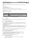
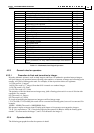
The A/D samples the following:
Signal Description
Ia,Ib,Ic The three phase currents, sampled simultaneously
Ain,ref The analog input and the reference voltage are sampled simultaneously to
form a differential measurement
Bus voltage The bus voltage is sampled to correct the current loop gain.
Table 2-1: Analog sampled signals
The resolution of all the measurements is 12bit, and in practice the last bit is noisy.
The motor currents are measured offset-free, because of a special measurement mechanism.
The analog inputs cannot avoid an offset, due to electronic inaccuracies in the Harmonica
circuits. This offset can be corrected using the AS[1] parameter, to the resolution of about
5mv.
The ability to correct offsets by AS[1] is limited to the resolution of 5mv, and about 10mv in
practice. This means that, for example, if AG[2]=10000, the offset correction quality to
speed analog reference will be limited to about 100count/sec.
2.8 Digital inputs
The Harmonica has six digital input connector pins. All the input pins are routed to a digital
input port. In addition two pins (5 and 6) are routed to high speed capturing input for main
and auxiliary homing. You can associate special functions to digital input pins, like Enable,
Stop, RLS, and FLS – refer the IL command in the Command Reference Manual.
The digital input response time is limited by the speed of the optical couplers, and also by
the input filters.
The encoder index and home input are filtered similarly to the position decoders. The timing
of the position decoder filters is explained in the EF[N] documentation in the command
reference.
The other digital inputs are filtered in software only. The timing of software filtering is
explained in the IF[N] documentation in the command reference.
The use of the digital inputs is detailed in the chapter on Sensors, I/O, and Events.
2.9 Digital output
The Harmonica has two digital output connector pins.
These two pins can be used for non-committed digital outputs, or programmed by the OL
command for special functions, like activating external brakes.