


HARSFEN0602
attempts are made 10msec after the last motor shutdown, or 10msec after the last
failure of MO=1.
For safety reasons, we recommend to program the Inhibit function as "active low".
That prevents incidental motor starts when the input pin is disconnected, or its driving
source is powered-down.
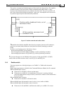
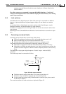
14.5 Limit switches
The Harmonica has 6 digital input pins. Each of the pins may be associated to a different
function. A pin may function as a general-purpose input, or it can function as a motion
limiter.
As a motion limiter, a digital input can stop the motion via the Stop-Manager, stop the
Reference Generator, or limit the motion to a single direction.
In addition to stopping the motion, the digital input can activate an automatic routine in the
user program.
Refer IL[N] in the Command Reference Manual to learn about function association to input
pins.
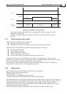
14.6 Connecting an external brake
Connecting an electrical brake to a motor helps safety where:
The load is unbalanced, and moves by its own weight when the motor is off.
Motor freewheeling can't be tolerated in malfunction cases.
Extreme motor deceleration is required in response to emergency event.
The brake activation must be synchronized to the motor-on/motor-off process.
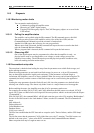
If the brake is engaged too much time after MO=0, the motor may "run away".
If the brake is released only after the motor is on, then if a position error existed, the
position controller integrated it. When the brake completely releases, the motor may
jump.
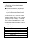
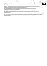
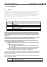
The Harmonica can program a digital output as a "brake" output – refer the OL[N]
command.
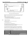
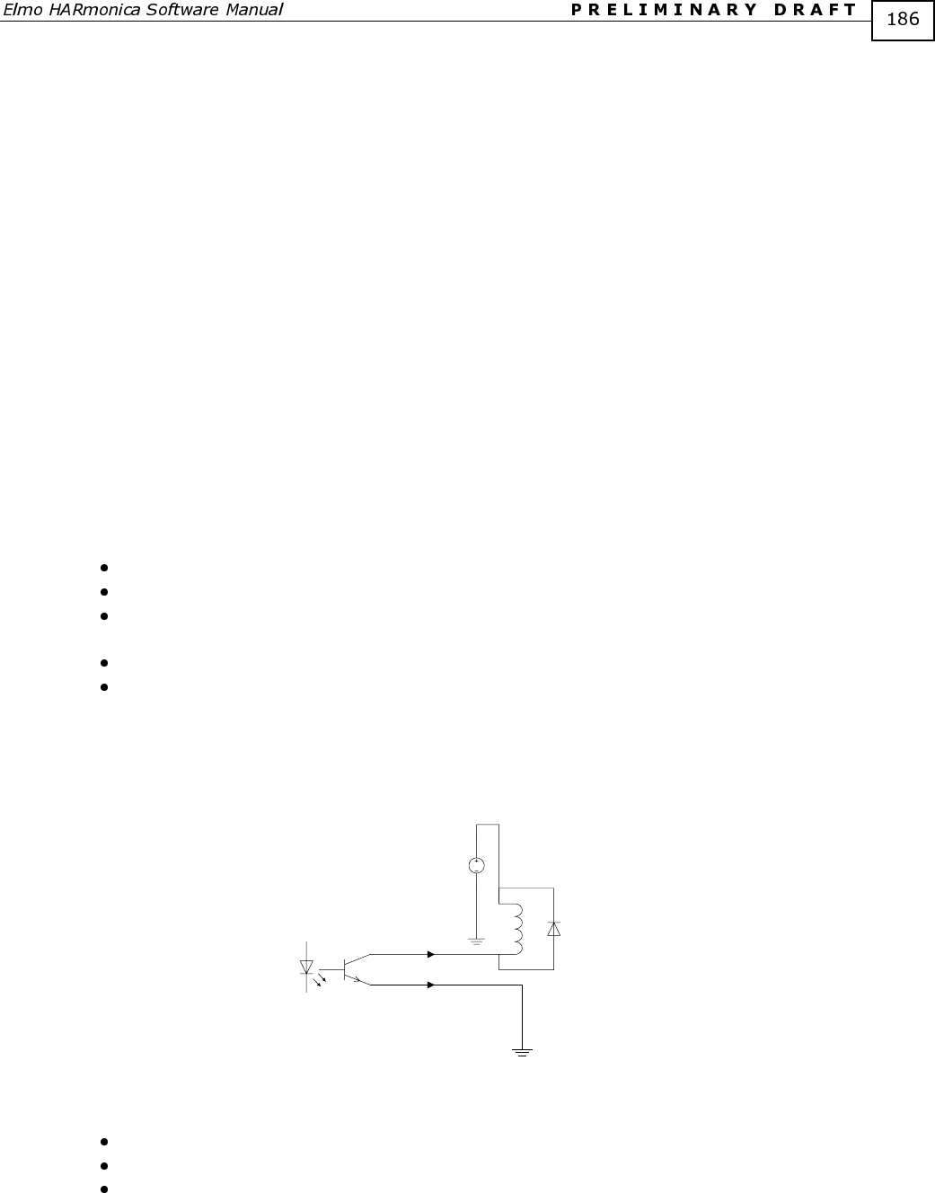
The brake output must be connected as follows:
DC
Harmonica
Output
opto-coupler
Brake relay - Normally
Engaged
Connector
pins
Figure 38: Brake output connection
The brake must be engaged when there is no current in the brake coil.
The brake relay coil must be equipped with a freewheeling diode.
For the current and voltage rating of the Harmonica connector pins, please consult
the Harmonica Manual.
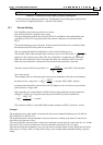
The normal waveforms for brake activation are depicted in Figure 39.