


HARSFEN0602
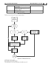
12.1.6.5.2 Programming Sequence for The Auto Increment PVT Mode
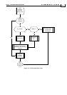
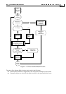
PVT motion must start with initial programming of the PVT arrays.
Set
MP[1] = First valid line in the PVT table
MP[2] = Last valid array in the PVT table
MP[3] = 1 for cyclical mode.
MP[4] = Not relevant for PVT (PT only)
MP[5] = Number of left programmed motion rows to issue a “PVT queue low” Emergency object. Set to
zero if no “PVT queue low” warning is desired.
MP[6]=the write pointer. This is the next position in the PVT table to be written by the CANopen object
0x2001.
Set the QP[N], QV[N], and QT[N] array elements for at least the first used two rows of the PVT table. This
is since PVT requires at least two time points to interpolate the motion trajectory.
Set (if not already set) UM=4 or UM=5, and MO=1
Set PV=N, assuming QP[N] ,QV[N] ,QT[N] and QP[N+1] ,QV[N+1] ,QT[N+1] are all programmed to valid
values.
Start the motion by a BG.
Use the CAN PVT/Auto increment command for the rest of the PVT motion.
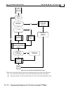
Keep informed how the PVT motion advances, either by receiving the read and the write PVT table pointers
continuously, mapped to a synchronous PDO, or by using the queue low emergency signal to signal the need
for more data. The queue low emergency message includes the present location of the read pointer and the
write pointer.
It is safe to send more PVT data PDOs until the write pointer is one location before the read-pointer
specified by the queue low emergency message. The host is well aware to the location of the write pointer,
since it can count its own messages. A data message may be, however, rejected since the queue is full, or
since a message is lost. In that case, the Amplifier will issue an emergency object to the host. After receiving
the emergency object the true location of the write pointer may be unclear. The host may then set MP[6] to
the possibly rejected table row and continue the writing from there.
Do not set MP[5] (Number of rows left for queue low emergency) too high. For example, consider a slow-
responding host managing a 64 rows long PVT queue in the Amplifier. Suppose that the PVT row times are
10 msec each, and that MP[5]=55. The host gets a queue low emergency object telling that there are 64-55+1
= 8 free to program rows in the PVT table. Suppose that the host takes 50msec to respond, and 5 msec to
program each row. Thus, the 8 rows have been programmed in 90 msec. In the meantime, 9 additional PVT
table rows have been executed, and there are only 54 valid rows in the PVT table. As 54 is lower than
MP[5], there will be no more queue-low emergency messages until the PVT table is exhausted, and the PVT
mode is terminated. This situation may be remedied if the host asks the Amplifier for PV (location of read
pointer) after the PVT table writes are complete. If PV<MP[5], the programming process took too much
time, and the writing must be continued.
Accurate timing with respect to the host is the essence of multiple-axis synchronized motion. Accurate
timing may be achieved by using the CAN SYNC signal, and the CAN synchronized BG service, as
described in the CAN Manual.
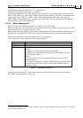
12.1.6.6 The Parameters of The PVT Motion Mode
The following parameters apply to PVT motion
What How Comment
Unit Mode (UM) Unit modes 3, 4 and 5 select
the position modes.