


HARSFEN0602
11 Unit Modes
The feedback structure of the amplifier can be arranged in several options. Those options are
called "unit modes" and programmed by the parameter UM. Switching the unit mode is
possible only with the motor off, since the feedback structure need be re-arranged.
The following unit modes are available:
Value Description (Related commands)
1 Torque control mode.
2 Speed control mode.
3 Micro Stepper mode.
4 Dual feedback position control.
5 Single feedback position control.
11.1 Torque control: Unit mode 1
In this mode the amplifier controls the motor torque only.
In this mode the amplifier may serve as a torque driver, controlled by an external controller.
Commutation is performed to get the maximum torque for the commanded motor current.
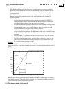
If position sensors are connected, the position and the speed are evaluated, and the amplifier will
abort upon over-speed, as specified by the parameters LL[2] and HL[2]
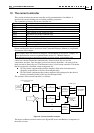
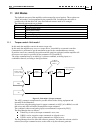
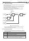
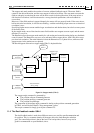
The torque command may be set either by a software command, an analog input, or a
combination thereof, according to the figure below:
TC
Analog input 1
(-10 to 10 Volts)
AG[1]
Amp/Volt
Enable if
RM==1
Torque command
(DV[1], Amp)
AS[1]
`
-
Stop
Manager
Figure 15: Unit mode 1 (Torque) structure
The AS[1] parameter compensates for possible offsets in the driving equipment and
internally in the Harmonica.
If you are not using the analog input for torque command, set AG[1] =0 or RM=0, to avoid
that noises and offset will affect the amplifiers torque command.
The combined (software and analog input) current demand is reported by DV[1].
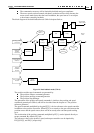
The Stop Manager does as follows:
If hard-stop is active, the torque command is set to zero
If RLS is active, negative torque commands are clipped to zero
If FLS is active, positive torque commands are clipped to zero.
The Stop-Manager does not affect the reference generator, and when the relevant switch is
released, the torque command restores to the value set by the reference generator.