Introduction
2
1.5 Outside Enclosure Overview
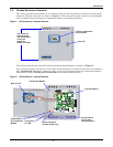
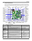
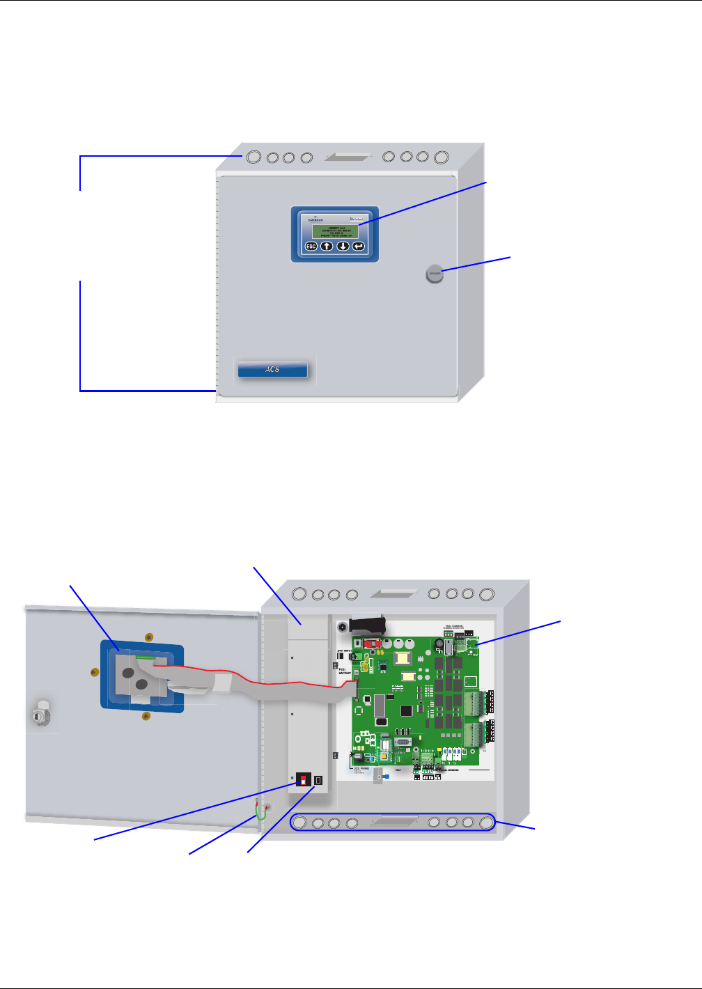
The AC8’s controller board comes in an enclosure that is 2-3/4" deep and has a built-in liquid crystal
display (LCD) and a key lock, as shown in Figure 1. The enclosure is made of metal to accommodate
secure conduit fittings and protect components against environmental debris.
Figure 1 AC8 enclosure—external features
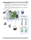
The enclosure houses the controller board and Transformer Module, as shown in Figure 2.
The enclosure must be secured to a wall, either flush-mounted or recessed in the wall, as described in
2.0 - Installation. Knockouts and access slots on the top and bottom allow easy connection of wires
and cables (see 3.0 - Wiring and Connections) with either mounting type.
Figure 2 AC8 enclosure—internal features
LCD for configuration
and operation
Key lock
The enclosure
has knockouts
and access slots
on top and
bottom for
cables and wires.
BAR CODE
BAR CODE
LIEBERT
START
TB7:
V INPU
UT
T
24V
V INPU
UT
T
+
—
+
—
(TOP)
ON
(BOTTOM)
0: COMMS
MS
485
TB3:
RELAY
OUTPUTS
TB2:
CONTACT
INPUTS
ASS REV
(BOTTOM)
(TOP)
4
3
2
1
(BOTTOM)
8
7
6
5
(BOTTOM)
(TOP)
4
3
2
1
(BOTTOM)
8
7
6
5
J11: PHONE
PIN 3-TIP
PIN 4-RI"N"G
MODEM
TB5: COMMON ALARM
(TERMINAL BLOCKS ROTATED IN VIEW)
(BOTTOM)
BOTTOM
Q11
R26
R402
P11
+
LS1
NO
NO
NO
N
ALARM
SENS
TOP
ENABLE
AUDIBLE
(TOP)
NO C NC NO C NC
ALL CIRCUITS;
CLASS 2
TB9: ANALOG
GROUND
+ +
——
+
—
+
—
3-4 BOTTOM
1-2 TOP
Back of LCD
Transformer Module
Controller Board
Ground wire
for LCD
On/Off switch
for Transformer
Module
Knockouts and
access slots
(top and bottom)
Power receptacle
(115VAC model only)


