


PMC-CGM Installation and Use (6806800D53C)
Hardware Preparation and Installation Configuring the Module
28
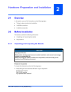
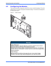
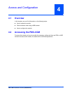
2.3 Configuring the Module
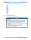
The module provides the configuration switch SW1 as shown in the following figure. The switch
settings shown in the figure correspond to the default settings. The switches are displayed as
the small white squares.
Figure 2-1 Switch Location
Product Malfunction
Switches marked as 'reserved' might carry production-related functions and can
cause the product to malfunction if their setting is changed.
Therefore, do not change settings of switches marked as 'reserved'. The setting of
switches which are not marked as 'reserved' has to be checked and changed before
product installation.
Product Damage
Setting/resetting the switches during operation can cause product damage.
Therefore, check and change switch settings before you install the product.