


Connector Pin Assignments
User Manual 27
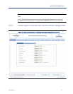
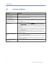
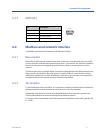
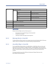
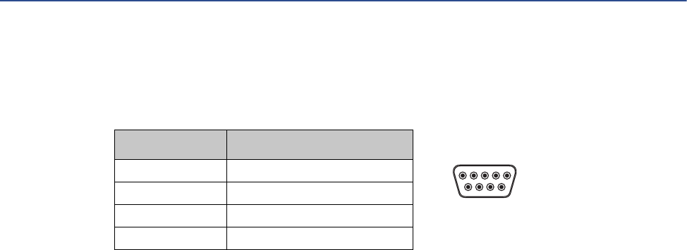
A.3.3 DBF9 (PC)
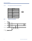
A.4 Modbus serial network interface
The Modbus serial network is based on an RS-485 physical layer.
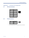
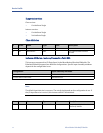
A.4.1 Bias resistors
When idle, RS-485 enters an indeterminate state, which may cause the serial receivers to pick
up noise from the serial lines and interpret this as data. To prevent this, the serial lines should be
forced into a known state using pull-up and pull-down resistors, commonly known as bias
resistors.
The bias resistors forms a voltage divider, forcing the voltage between the differential pair to be
higher then the threshold for the serial receivers, typically >200 mV. Note that bias resistors
shall only be installed on one node. Installing bias resistors on several nodes may compromise
the signal quality on the network and cause transmission problems.
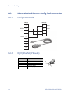
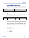
A.4.2 Termination
To avoid reflections on the serial lines, it is important to properly terminate the sub-network by
placing termination resistors between the serial receivers near the end nodes.
Additionally, if the distance from the EtherNet/IP Module to the transmitter is greater than
100 feet, Micro Motion recommends adding the termination resistors.
The resistor value should ideally match the characteristic impedance of the cable, typically 100
to 120 Ω.
Pin Description
1Ground
2Ground
3 RS-232 Rx (Input)
4 RS-232 Tx (Output)
96
15 (female)