


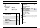


EPSON AcuLaser C1100 Revision B
TROUBLESHOOTING FIP according to the printer message 168
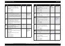
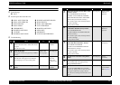
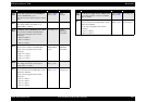
FIP-29
Panel Message
Jam E
Jam D, E
Possible parts that caused the error
Troubleshooting
ROLL ASSY PRE-REGI ROLL-PINCH
ROLL-REGI METAL ROLL REGI RUBBER
ACTUATOR-REGI SENSOR REGI
MOTOR-PH HARNESS-ASSY P/H1
HARNESS-ASSY P/H2 PWBA MCU
LV/HVPS HARNESS ASSY MAIN
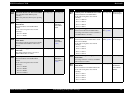
Step Check Yes No
1
Paper size check
Is the paper size compliant with the
specifications?
Go to Step[2]. Use paper of
size compliant
with the
specifications.
2
Paper size setting check
Does the size of the paper in use match the
size of the paper set on the control panel?
Go to Step[4]. Change the
paper size
setting, and
proceed to step
[3].
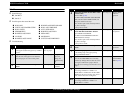
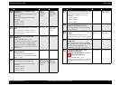
3
Does the error recur when a test print is
made by dialog operations?
Go to Step[4]. End of
procedure
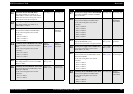
4
Shape and operation check of ROLL ASSY
PRE-REGI and ROLL-PINCH
Open CHUTE ASSY-REAR.
Are ROLL ASSY PRE-REGI and ROLL-
PINCH attached correctly?
Also, do these parts rotate smoothly without
any dirt or damage?
Turn by hand to check.
Go to Step[5]. Replace or re-
attach ROLL in
question.
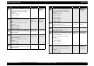
5
Shape and operation check of ROLL-REGI
METAL and ROLL REGI RUBBER
Open CHUTE ASSY-REAR.
Are the ROLL-REGI and ROLL REGI
RUBBER attached correctly?
Also, do these parts rotate smoothly without
any dirt or damage?
Turn by hand to check.
Go to Step[6]. Replace or re-
attach ROLL in
question.
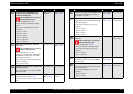
6
Operation check of ACTUATOR-REGI
Does ACTUATOR-REGI move smoothly
without any damage? Does ACTUATOR-
REGI enter the sensor sensing area when there
is paper? Does it leave the sensor sensing area
when there is no paper?
Go to Step[7]. Replace
ACTUATOR-
REGI. (p.335)
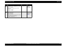
7
Operation check of SENSOR REGI
The voltage of P408-12 ↔ P408-11 on
PWBA MCU is 0 VDC when ACTUATOR
REGI enters the sensing area of SENSOR
REGI, and is 5 VDC when it leaves the
sensing area?
Go to Step[8]. Go to Step[11].
8
24 VDC power supply check to MOTOR-PH
The voltage of P409-6 ↔ P409-5 on PWBA
MCU is 24 VDC?
Go to Step[9]. Go to Step[14].
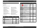
9
Continuity check of HARNESS-ASSY P/H1
Disconnect P/J405 and P/J604 from PWBA
MCU.
Do all of the wiring below have normal
continuity?
J409-1 ↔ P604-6
J409-2 ↔ P604-5
J409-3 ↔ P604-4
J409-4 ↔ P604-3
J409-5 ↔ P604-2
J409-6 ↔ P604-1
Go to Step[10]. Replace
HARNESS-
ASSY P/H1.
Step Check Yes No