


EPSON AcuLaser C1100 Revision B
DISASSEMBLY AND ASSEMBLY ELEC 411
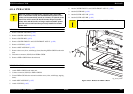
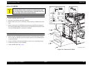
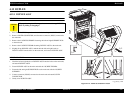
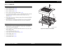
4.11.9 CHASSIS ASSY ESS (REFERENCE ONLY)
REMOVAL
1. Remove COVER ASSY LH. (p.295)
2. Disconnect all connectors from the PWBA ESS.
3. Remove disconnected connectors from the hole on CHASSIS ESS.
4. Unclamp the clamp on CHASSIS ASSY ESS, and remove the harness.
5. Remove the 5 screws (silver, with flange, 6 mm) fastening CHASSIS ASSY ESS
to the main unit.
6. Remove CHASSIS ASSY ESS from the main unit.
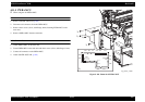
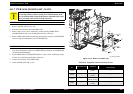
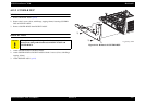
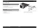
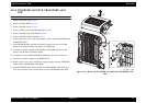
REINSTALLATION
1. Matched the protrusion on CHASSIS ASSY ESS with the hole on the main unit,
and attach CHASSIS ASSY ESS.
2. Fasten CHASSIS ASSY ESS to the main unit with the 5 screws (silver, with
flange, 6 mm).
3. Insert disconnected connectors from the hole on CHASSIS ESS.
4. Connect all connectors to the PWBA ESS.
5. Fasten the harness with the clamp on CHASSIS ASSY ESS.
6. Attach COVER ASSY LH. (p.295)
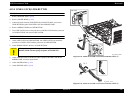
Figure 4-114. Removal of CHASSIS ASSY ESS
C A U T I O N
Avoid staticky places such as on a carpet especially when removing
or inserting a Board. Before starting work with the Board, make
sure to touch metallic portion of the printer connected to the earth
to let your body come out free of static electricity.
C A U T I O N
When performing the following work, take care to prevent the
harness from being sandwiched between the main unit and
CHASSIS ESS.
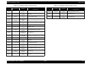
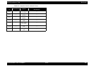
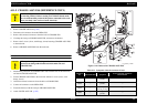
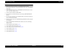
Table 4-11. Symptoms when the connector is loose
Connector
No.
Panel Indication Symptom
Error Caused by Connector
Disconnection
CN405 ---
Printing is not
possible.
---
CN501 ---
Printing is not
possible.
---
CN502 ---
Paper is ejected
without printing.
---
CN601 ---
Printing is not
possible.
---
Leg_Sec03_114EB
3)
2)
2)
5)
4)
5)
6)
5)
1)
5)
5)