


Matrix 12800 Switchers • Virtualization/Control Software
3-2
Virtualization/Control Software
PRELIMINARY
Explaining Virtual I/O Switching
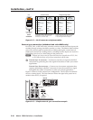
A Matrix 12800 system consists of from one to nine BMEs, each of which can have
as many as 128 inputs and 128 outputs. It is usually desirable to have certain inputs
switch together as a set, to follow each other. For example, if the system consists of
a 128 x 128 video BME and a 128 x 128 audio BME, you want your video images on
your video monitors to match the audio from the sound system (for example, video
and audio from a DVD). You would want the video and audio to follow each other
when they are switched to another display. This type of switching requires the two
BMEs to communicate with each other so that they both switch to the correct inputs
simultaneously. In the traditional and simplest configuration, hardware is usually
designed to switch both BMEs to the same input.
S-video presents an example in which follow is always required. The luminance
(Y) and chrominance (C) signals must be switched as a pair of signals. Traditional
hardware does this by causing the paired signals to follow each other, either in a
single box made only for S-video or by using two composite video switchers and
forcing them to follow each other.
A better solution would be to have a single video matrix switcher box that can be
field-programmed to be either an S-video switcher, a composite video switcher, or
some combination of both. That is what the Extron Virtualization/Control software
does;itgroupsphysical input connectors and physical output connectors together into
virtual inputs and virtual outputs, each of which switches from one (composite video)
to seven (RGBHV and stereo audio) virtual planes. The software then downloads
the virtual map to the system memory of the Matrix 12800.
AssumeaMatrix12800videoswitcherandaMatrix12800audioswitcher;to
support the S-video example above, the Virtualization/Control software can map
(logically split) the video switcher into a Y plane and a C plane, and the audio
switcher into two (left and right channels) audio planes. This creates a system with
up to 64 virtual inputs and 64 virtual outputs in 4 virtual planes (Y, C, and left and
right channel audio). (The limit of 64 inputs and outputs comes from splitting
the 128 x 128 video BME into 2 halves.) In this example, half of the audio BME
is not included in the virtual map since only 64 of the 128 ports are used, so the
configuration would be more cost-effective with a 64 x 64 audio BME.
As an alternative, using the same Matrix 12800 video and audio switchers, the
software can map the system into a composite video matrix consisting of up to 128
virtual inputs by 128 virtual outputs in 3 virtual planes (video and audio).
The software can also map the same two switchers into a component video system
consisting of up to 42 virtual inputs by 42 virtual outputs in 5 virtual planes (Y, R-Y,
B-Y, and left and right audio). In this configuration two physical input BNCs and
two physical output BNCs are not used. As in the S-video example, the audio plane
would be served more cost-effectively using a 64 x 64 audio BME.
Lastly, the software can map the same two switchers into a 25-input-by-25-
output component video system, a 20-input-by-20-output S-video system, and a
13-composite-input-by-13-composite-output system, each with audio (58 virtual
inputs by 58 virtual outputs). In fact, the video switcher can be subdivided to
accommodate any combination of video formats so long as the total number of
virtual inputs and virtual outputs does not exceed the number of physical inputs
and outputs (up to 128 x 128).
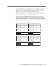
The number of physical input connectors required can be calculated with the
equation Vi * Vp = Pi, where Vi is the number of virtual inputs, Vp is the number of
virtual planes, and Pi is the number of physical inputs required. The equation for
output connectors is Vo * Vp = Po.