


3-3
Matrix 12800 Switchers • Virtualization/Control Software
PRELIMINARY
The largest possible system consists of three 128 x 128 video BMEs, two 128 x 128
sync BMEs, and one 128 x 128 audio BME. This system can then be mapped to
become a matrix with 128 virtual inputs and 128 virtual outputs in seven virtual
planes (R, G, B, H, V, left-channel audio, and right-channel audio).
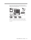
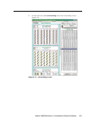
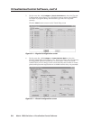
All of these configurations are established by creating a virtual map with the
Virtualization/Control software and downloading the virtual map to the BME. The
Virtualization/Control software is included with each switcher.
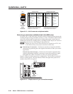
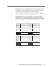
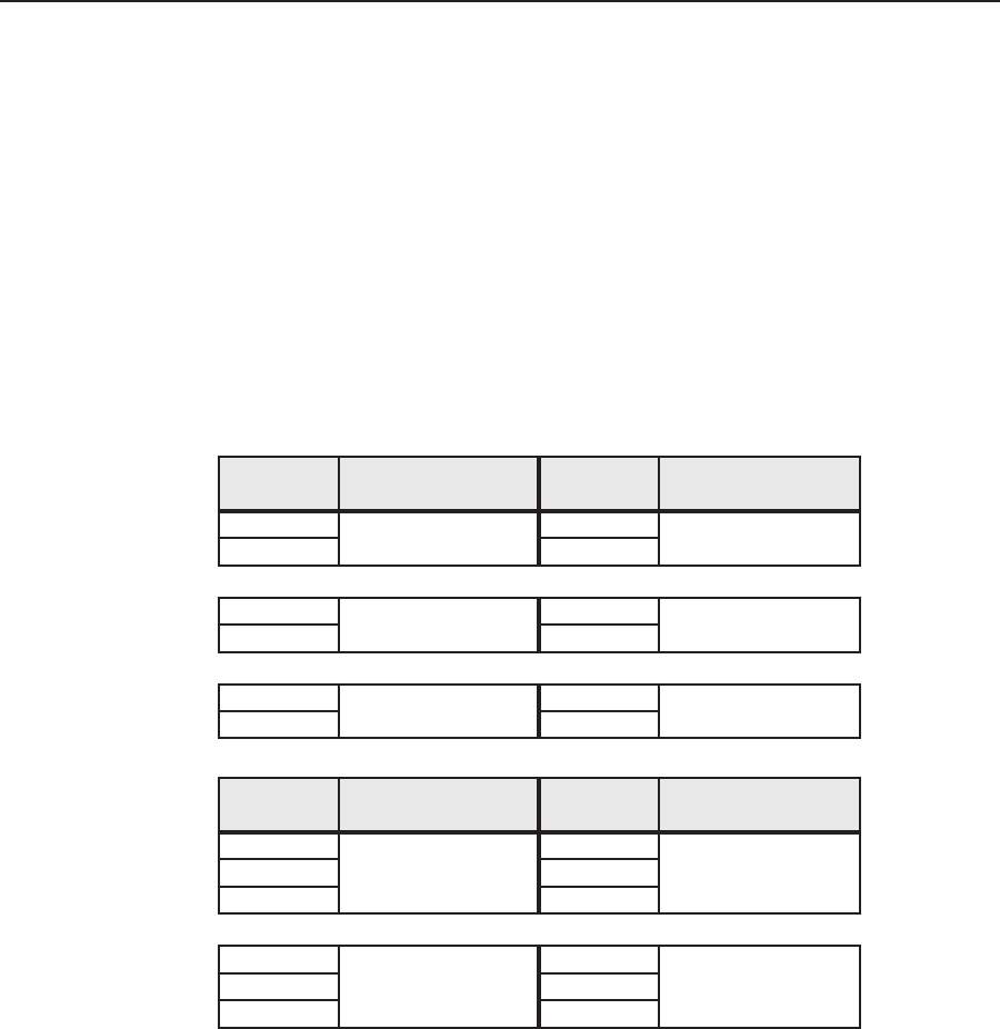
Note that the number of virtual planes identifies how many physical input (or
output) connectors are switched for each virtual input switched. The following
table shows how the physical and virtual inputs and outputs differ in a video BME
in the 64 x 64 S-video matrix and 42 x 42 component video virtual matrix examples
above. In either example, the audio BME (not shown) has physical input 1 as virtual
input 1, 2 as 2, and so on.
oediv-S
lacisyhP
tupni
lautriV oediv-S
tupni
lacisyhP
tuptuo
lautriV oediv-S
tuptuo
)Y(1
1
)Y(1
1
)C(
2)
C(2
)Y(3
2
)Y(3
2
)C(
4)
C(4
)Y(5
3
)Y(5
3
)C(
6)
C(6
oedivtnenopmoC
lacisyhP
tupni
lautriV tnenopmoc
tupnioediv
lacisyhP
tuptuo
lautriV tnenopmoc
tuptuooediv
)Y(1
1
)Y(1
1)Y-R(
2)
Y-R(2
)Y-B(
3)
Y-B(3
)Y(4
2
)Y(4
2)Y-R(
5)
Y-R(5
)Y-B(
6)
Y-B(6