4-15
Matrix 12800 Switchers • Programming Guide
PRELIMINARY
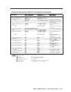
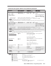
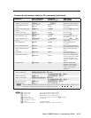
Coand ASCII coand
(hot to witcher)
Response
(witcher to hot)
Additional
decription
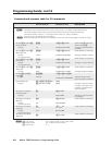
Resets
Intialize virtual map size
EX!
*
X@
ZM
}
Zpm
X!
*
X@]
Intialize the virtual map size.
Reset global presets and
names
E
ZG
}
Zpg
]
Clear all global presets and
their names.
Reset an individual global
preset
EX(
ZG
}
Zpg
X(]
Clear preset
X(
and its name.
Reset all room map
E
ZR
}
Zpr
]
Clear all rooms.
Reset individual room map
EX1)
ZR
}
Zpr
X1)]
Clear room
X1)
.
Reset all room presets
E
ZP
}
Zpp
]
Clear all room presets and
their names.
Reset individual room
preset
EX1)
*
X1@}
Zpp
X1)
*
X1@]
Clear room
X1)
, preset
X1@
!
and its name.
Reset RGB delays
E
ZD
}
Zpd
]
Reset all RGB delays to
0.0 seconds.
Reset audio input levels
E
ZA
}
Zpa
]
Reset all audio input levels
(gain and attenuation) to 0 dB.
Reset all RGB and audio
mutes
E
ZZ
}
Zpz
]
Reset all video and audio
mutes.
Reset flash
E
ZFFF
]
Zpf
]
Reset flash memory
(erase user-supplied files).
Reset whole switcher
E
ZXXX
}
Zpx
]
Clear all ties and all presets,
resets all audio gains to 0 dB,
resets the RGB delay, and
unmutes all video and audio
outputs.
Absolute reset
E
ZQQQ
}
Zpq
]
Similar to Reset whole
switcher, plus sets the IP
address to 192.168.254.254
and the subnet mask to
255.255.0.0.
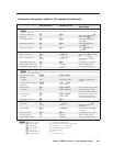
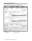
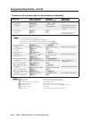
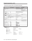
Virtual control
Write virtual inputs
EX@
,
X1(
,
X1!
,
X2)
1
,
X2)
2
...
X2)
n
MI
}
Mpi
X@
,
X1(
,
X1!
,
X2)
1
,
X2)
2
...
X2)
n
]
Read virtual inputs
EX@
MI
} X1(
,
X1!
,
X2)
1
,
X2)
2
...
X2)
n
]
Write virtual outputs
EX#
,
X1(
,
X1!
,
X2)
1
,
X2)
2
...
X2)
n
MO
}
Mpo
X#
,
X1(
,
X1!
,
X2)
1
,
X2)
2
...
X2)
n
]
Read virtual outputs
EX#
MO
} X1(
,
X1!
,
X2)
1
,
X2)
2
...
X2)
n
]
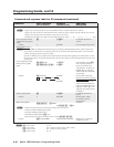
Read plane types
E
MC
}
letter and BME# pairs
N
A letter and BME# pair consists of a letter that identifies the video or audio plane (Red, Blue, Mono, Audio, and so on)
and a number that identifies the BME assigment. Example: R0G1B2S3A4.
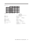
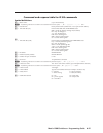
Coand and repone table for SIS coand (continued)
N
X@
= Output number 001 through maximum number of outputs
X%
= Input number 001 through maximum number of inputs
X(
= Preset # 32 maximum (0 = current configuration)
X1)
= Room number 32 max. (Each can have up to 10 presets (
X1@
s) assigned.)
X1@
= Room preset number 10 maximum
X1(
= Signal type. See page 4-7.
X1!
= Name 12 characters maximum
X2)
= Virtual input or output Example: 4i003 (BME 3, input connector 003)


