


Installation, cont’d
System 5
cc
cc
c
rr
rr
r Plus • Installation2-2
TX
RX
IR
LEARN
CONFIG
RETRY
COMPUTERAUDIO
PC1 INPUT
Plus
SYSTEM 5
Installation
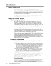
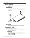
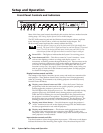
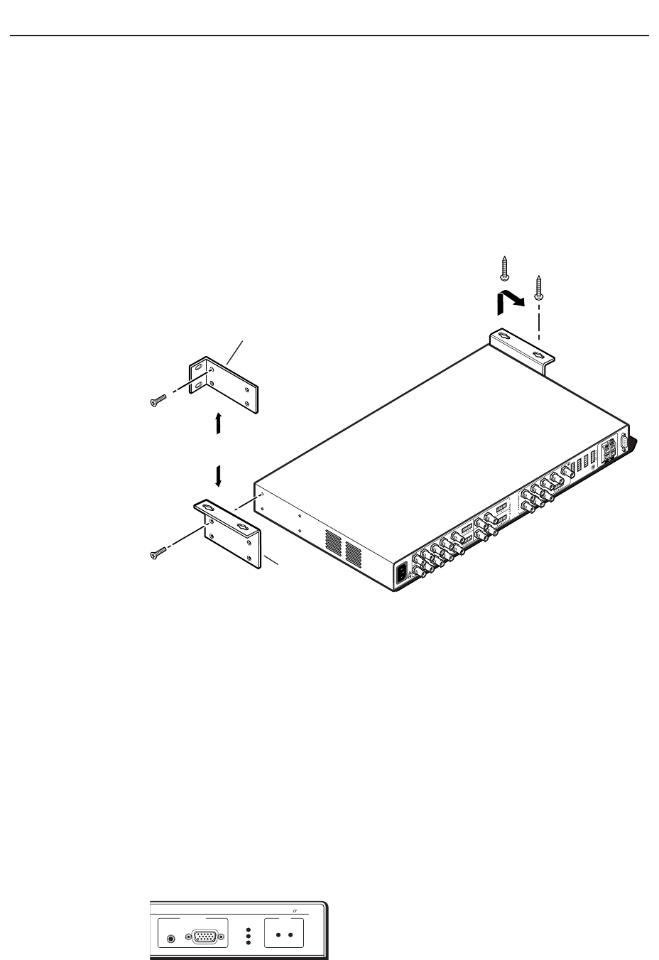
Mounting the Switcher
The System 5cr Plus comes with two sets of mounting brackets. One set is for
mounting the switcher under a table or on (against) a wall, and the other set is for
rack-mounting.
Table/wall mounting
The table/wall-mounting brackets extend approximately 1/4” (6.3 mm) above the
top surface of the System 5 enclosure, as shown below. This design allows for an
air space between the enclosure and the surface on which it is mounted. Attach the
table/wall-mounting brackets to the switcher with the provided machine screws,
as shown below.
#8 Screw (4 Plcs)
Each Side
Mounting Screws
(2 Places)
Each Side
or
Rack-mount
Bracket
Table/
Wall-mount
Bracket
50/60 Hz
100-240V 1.3A
RS-232
R
GB
PC 2
PC 3
VID 1
VID 2
H/HV
V
R
GB
H/H
V
V
LR
RG
B
H
/HV
V
V/Y
V/Y
C
C
Y
C VID
PREAMP OUT
L
R
LR
LR
L
L
R
R
L
R
AUX 1
AUX 2
AMPLIFIED OUT
DISPLAY PWR
SENSOR
RELAY COMM.
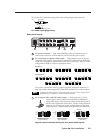
Mounting the System 5
crcr
crcr
cr
Plus
Rack mounting
The switcher can also be rack mounted. Attach the rack-mounting brackets to the
switcher with the provided machine screws, as shown above, then fasten the
switcher to the rack using the supplied machine screws.
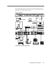
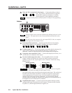
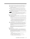
Cabling and Panel Views
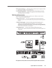
Power, video, and audio connections
With the exception of input PC 1 on the front panel, all input and output connectors
are on the rear panel. The LEDs adjacent to the corresponding buttons on the front
panel light when each input is active.
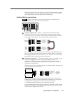
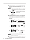
Front panel inputs
The PC 1 input on the front panel accepts computer video (RGBHV, RGBS or RGsB)
through a VGA 15-pin HD connector, and
unbalanced stereo audio through a 3.5 mm mini
stereo jack, as shown in the illustration at left.