


Serial Communication, cont’d
System 5
cc
cc
c
rr
rr
r Plus • Serial Communication4-2
Serial Communication
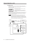
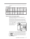
The System 5cr Plus can be remotely controlled via a host computer or other device
(such as a control system) attached to the rear panel RS-232 connector. The control
device (host) can use either Extron’s Simple Instruction Set (SIS) commands or the
graphical control program for Windows.
The System 5 switcher uses a protocol of 9600 baud, 1 stop bit, no parity, and
no flow control.
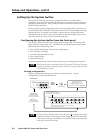
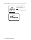
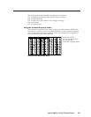
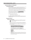
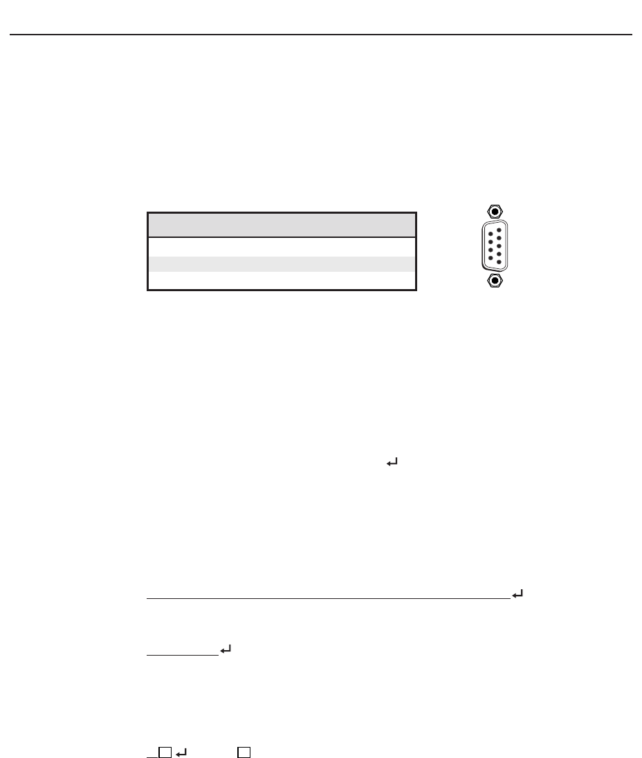
The rear panel RS-232 9-pin D connector has the following pin assignments:
Pin RS-232 function Description
2 Tx Transmit data
3 Rx Receive data
5 Gnd Signal ground
DB9 Pin Locations
Female
5
1
9
6
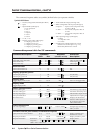
RS-232 Programmer’s Guide
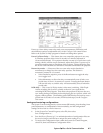
Host-to-switcher communications
SIS commands consist of one or more characters per field. No special characters
are required to begin or end a command sequence. When the System 5cr Plus
determines that a command is valid, it executes the command and sends a
response to the host device. All responses from the switcher to the host end with a
carriage return and a line feed (CR/LF = ), which signals the end of the response
character string. A string is one or more characters.
Switcher-initiated messages
When a local event such as a front panel (or SCP control pad) selection or
adjustment takes place, the System 5 switcher responds by sending a message to
the host. No response is required from the host. The switcher-initiated messages
are listed here (underlined).
(C) Copyright 2000, Extron Electronics, System 5cr Plus, Vx.xx
The System 5 sends the copyright message when it first powers on. Vx.xx is the
firmware version number.
RECONFIG
When a change is made via a front panel control or another operation occurs that
must be written to a new memory block, the System 5 sends the reconfiguration
message. No response is required from the RS-232 host, but the host may request a
new status listing via the request information command (I/i). See the command/
response table in this chapter for details.
C
X1
(where
X1
is the input number)
The System 5 sends this response when an input is switched. C = both audio and
video were switched.
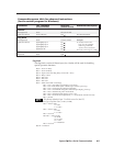
Error responses
When the switcher receives a valid SIS command, it executes the command and
sends a response to the host device. If the System 5 is unable to execute the
command because the command is invalid or it contains invalid parameters, it
returns an error response to the host.