


Installation, cont’d
System 5
cc
cc
c
rr
rr
r Plus • Installation2-6
3
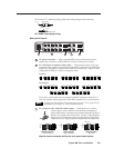
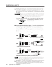
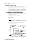
Display power sensor port — This mini stereo-style jack allows connection
of an optional display power (current) sensor (Extron part #60-271-01). The
power sensor is used to keep the projector and the System 5 in sync. Refer to
the Power Sensor User’s Guide, part #68-391-01, for information on operating
the sensor.
The power sensor port on the System 5 supplies +12VDC. To avoid electric
shock when connecting the cable from the power sensor into the System 5,
always connect the stereo jack at one end of the cable to the power sensor
unit before plugging the jack at the other end into the System 5.
The wiring connections are the same on both ends of the cable that connects
the power sensor to the System 5. Wire the
included connector as shown at left.
Use a 3-wire cable.
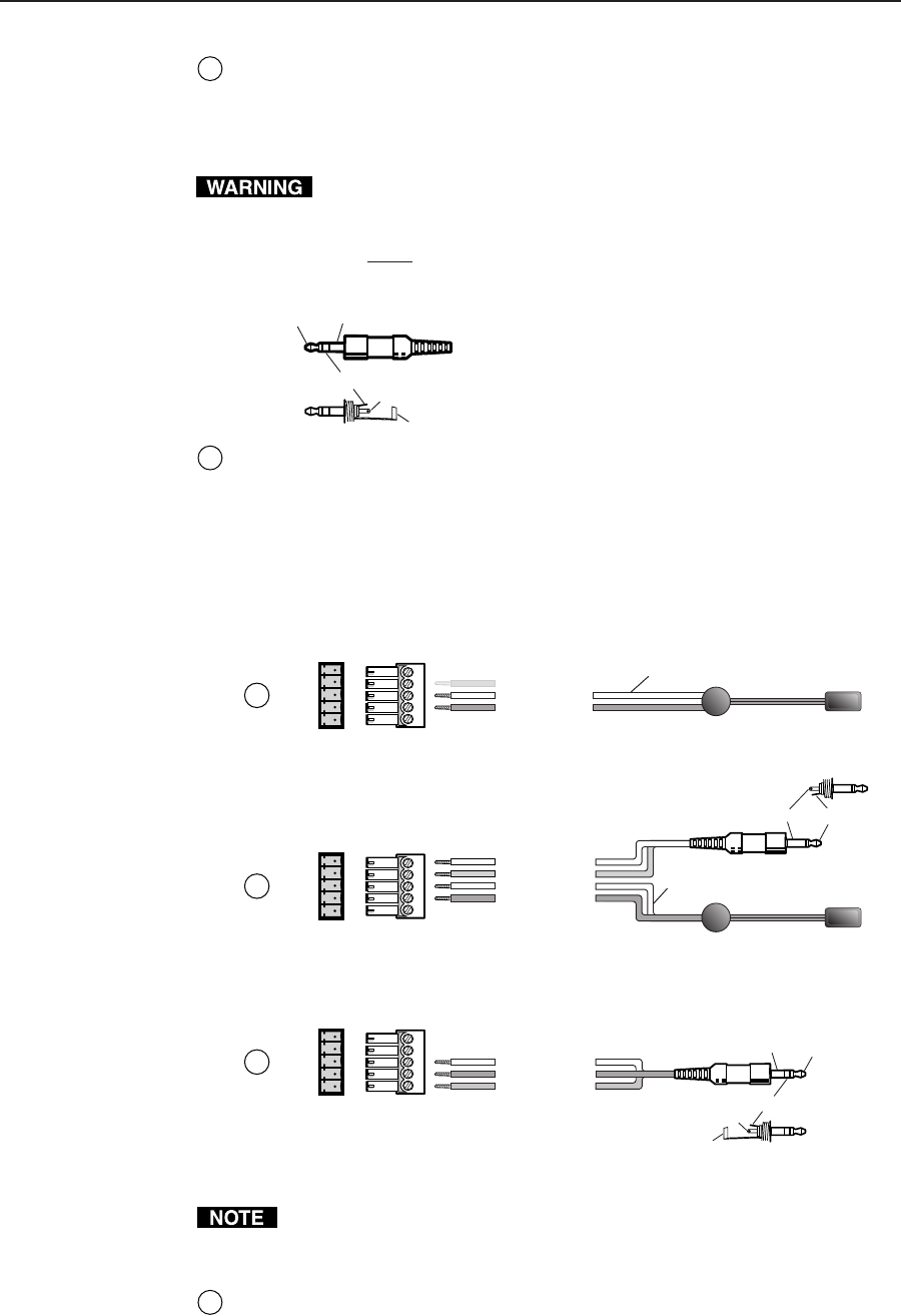
4
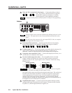
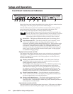
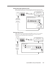
Projector communications port (Comm) — Connect the included IR Emitter
or optional IR Broadcaster via this captive screw connector to send learned/
uploaded IR signals (which differ from IR 401 remote control signals) to
control the projector. The signals from the optional IR Broadcaster cover a
wider area and greater distance than do those from the emitter, so it can be
placed further from the projector. The IR Broadcaster is often used to replace
the IR Emitter.
Wire the connector using one of the wiring options shown below.
Reserved/not used
Gnd*
Carrier & signal
Gnd*
+12V
System 5
Comm port
System 5
Comm port
For IR Emitter only
For IR Emitter and/or wired projector remote
COMM
IR Emitter
*Either the second or the fourth pole can be used for ground.
4A
A
B
C
D
E
White striped wire only
Signal
Gnd
Carrier & signal
Gnd
+12V
COMM
IR Emitter
To projector's
wired remote
control
Tip (signal)Sleeve (Gnd)
4B
A
B
C
D
E
White striped wire
System 5
Comm port
For IR Broadcaster
Reserved/not used
Gnd
Carrier & signal
Gnd
+12V
COMM
Tip (+12V)
Sleeve (Gnd)
Tip (+12V)
Ring (signal)
Sleeve (Gnd)
To the
IR Broadcaster
(60-272-02)
4C
A
B
C
D
E
Projector communications (Comm) port connections
For some projectors the emitter must be used together with the IR Broadcaster.
Refer to the IR Broadcaster User’s Guide (part #68-392-02) or contact an
Extron support representative for details.
5
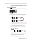
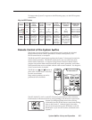
RS-232 port — Connect a device such as a computer or touch panel control to
the System 5 via this 9-pin D connector for serial RS-232 control. See the
Serial Communications chapter for information on how to install and use the
control software and the SIS commands.
Tip (+12V) Sleeve (GND)
Tip (+12V)
Ring (signal)
Sleeve (GND)