


A-5System 5
cc
cc
c
rr
rr
r Plus • Appendix
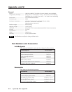
Firmware Upgrade Installation
In some cases the System 5’s firmware may require replacement with an updated
version. The two user-replaceable firmware chips are U1, the main microcontroller,
and U7, the carrier signal generator.
Changes to firmware must be performed by authorized service personnel
only.
Follow these steps to replace firmware in the System 5.
1. Disconnect the AC power cord from the System 5 to remove power from the
unit.
To prevent electric shock, always unplug the System 5 switcher from the
AC power source before opening the enclosure.
2. Remove the switcher from the rack, wall, or furniture.
3. Remove the cover of the switcher (the top half of the enclosure) by removing
the screws, then lifting the cover straight up.
Do not touch any switches or other electronic components inside the
switcher. Doing so could damage the switcher. Electrostatic discharge
(ESD) can damage IC chips even though you cannot feel it. You must be
electrically grounded before proceeding with firmware replacement. A
grounding wrist strap is recommended.
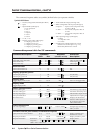
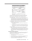
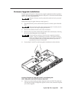
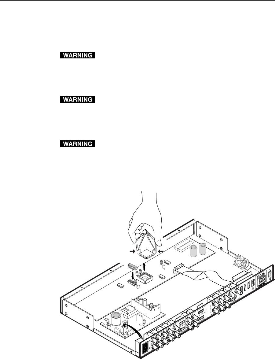
4. Locate chips U1 and U7 on the front panel circuit board, as shown below.
50/60 Hz
100-240V 1.3A
RS-232
R
GB
PC 2
PC 3
VID 1
VID 2
H
/H
V
V
R
G
B
H
/H
V
V
LR
R
G
B
H
/H
V
V
V/Y
V/Y
C
C
Y
C
VID
PREAMP OUT
L
R
L
R
L
R
L
L
R
R
L
R
AUX 1
AUX 2
AMPLIFIED OUT
DISPLAY PWR
SENSOR
RELAY
COMM.
U14
HIGH VOLTAGE
CAUTION
U70
Locating firmware IC chips U1 and U7, and aligning the
PLCC chip puller tool with firmware chip slots
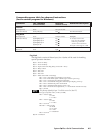
5. After you are electrically grounded, align the hooks of a PLCC IC puller tool
with the slots located in diagonally opposite corners of the firmware chip that
you wish to upgrade.