


2-3System 5
cc
cc
c
rr
rr
r Plus • Installation
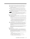
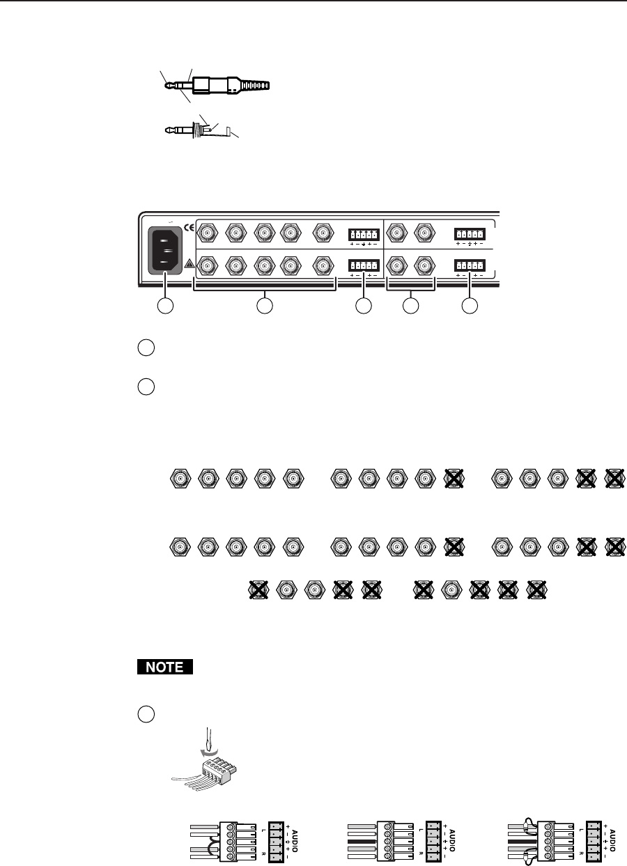
To wire the PC 1 audio input plug, follow the wiring diagram shown below.
Tip (+) Sleeve (GND)
Tip (L, +)
Ring (R, -)
Sleeve (GND)
PC1 audio input plug wiring
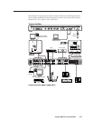
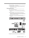
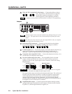
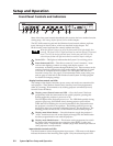
Rear panel inputs
1
AC power connector — Plug a standard IEC power cord into this port to
connect the switcher to a 100 to 240VAC, 50 Hz or 60 Hz power source.
2
PC 2 and Input 3 computer video inputs — These inputs accept VGA-type
computer-video signals, and each has 5 female BNC connectors for RGB video
input with composite or separate horizontal and vertical sync. Input 3 can be
configured for RGB or S-video or composite video.
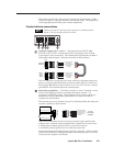
For PC 2:
RGB
H/HV
V
RGB
H/HV
V
RGBS
RGB
H/HV
V
RGBHV RGsB
(
S
y
nc on Green
)
For Input 3:
R B/C
H/HV
V
R B/C
H/HV
V
RGBS
R
G/Y
VID
G/Y
VID
G/Y
VID
G/Y
VID
G/Y
VID
B/C
H/HV
V
RGBHV RGsB (Sync on Green)
R B/C
H/HV
V
S-video (Y/C)
R B/C
H/HV
V
Composite Video
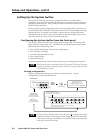
For S-video, connect the luma (Y) signal to the BNC connector marked G/Y
and Vid, and the chroma signal (C) to the BNC marked B/C, as shown above.
Configure the video format via the front panel (see page 3-5) or using RS-232
programming (see chapter 4, “Serial Communication”).
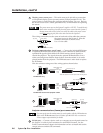
3
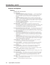
PC 2, Input 3, Vid 1, and Vid 2 audio inputs — Each input has a 3.5 mm,
5-pole captive screw connector for balanced or unbalanced
stereo audio input. Connectors are included with each System 5,
but the user supplies the audio cable. See the wiring diagrams
below to wire a connector for the appropriate input type and
impedance level. High impedance is generally over 800 ohms.
Unbalanced Input
Tip
Sleeve
Tip
Sleeve
Balanced Input
Tip
Ring
Sleeve (s)
Tip
Ring
Tip
Ring
Sleeve (s)
Tip
Ring
Balanced Input
(high impedance)
(high impedance) (600 ohms)
600 ohms
600 ohms
Captive screw connector wiring for rear panel audio inputs
50/60 Hz
100-240V 1.3A
RGB
PC 2
INPUT 3
VID 1
VID 2
H/HV
VLR
R
G/Y
VID
B/C
H/HV
V
V/Y
V/Y
C
C
LR
LR
LR
I
N
P
U
T
S
1 3 342