


Quick Start — System 5
cc
cc
c
rr
rr
r Plus
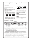
Installation
Step 1
Turn off power to the input and output devices,
and remove the power cords from them.
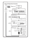
Step 2
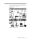
Attach the switcher to the input and output devices.
See “Power, video, and audio connections” in
chapter 2 for details and diagrams.
Input options are:
• RGB for PC 1 and PC 2
• RGB, S-video, or composite video for Input 3
• S-video or composite video for Vid 1 & Vid 2
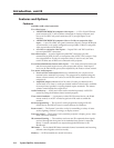
• Balanced/unbalanced stereo audio for all inputs
Unbalanced Input
Tip
Sleeve
Tip
Sleeve
Balanced Input
Tip
Ring
Sleeve (s)
Tip
Ring
Tip
Ring
Sleeve (s)
Tip
Ring
Balanced Input
(high impedance:
over 10 kohms)
(high impedance) (600 ohms)
600 ohms
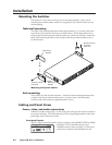
Output options are:
• RGBHV, RGBS, S-video, or composite video
• Balanced or unbalanced audio output via the
line level or amplified outputs.
Unbalanced Output
Tip
See Caution
Sleeve (s)
Tip
See Caution
Balanced Output
Tip
Ring
Sleeve (s)
Tip
Ring
CAUTION
Connect sleeve to ground (Gnd).
Connecting the sleeve to a negative
terminal will damage the circuits.
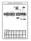
Step 3
With AC power still removed, connect control
devices and accessories, including an RS-232
controller. See “Control device connections” in
chapter 2 for details and wiring diagrams.
Step 4
Connect power cords and apply power to the
switcher, the input and output devices, and the
RS-232 controller.
Step 5
Set up (configure) the System 5cr Plus via front
panel controls, RS-232 SIS commands, or the
Windows-based control program.
(See the next page.)
VID
MAX.
CLIP
MIN.
TX
RX
IR
LEARN
CONFIG
RETRY
Y/C
VID
PC
Y/C
VID
Y/C
ROOM
DISPLAY
POWER MUTE MODE PC1 PC2 INPUT 3
VOLUME
AUDIO
COMPUTERAUDIO
PC1 INPUT
Plus
SYSTEM 5
VID1 VID2
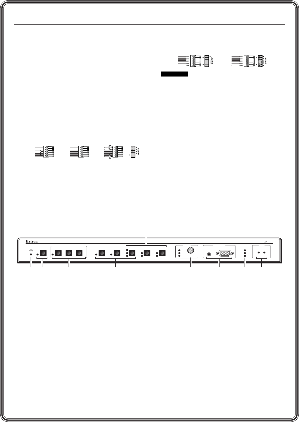
PC 1 (input 1)
RGB computer
video input with
audio
IR receiver
and IR
learning
ports
RGB computer
video inputs
with audio
IR
control
LEDs
Audio volume
master control
or control for
amplified output
Room
control
(for Room/
relay port)
See pages
2-6 and 4-7.
Display (projector)
controls
for setting and sending
learned IR commands
(once the button is
programmed)
Power
LED
S-video or composite
video inputs with audio
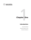
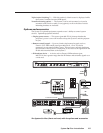
Front Panel Controls
See “Front Panel Controls and Indicators” in chapter 3 for details. Refer to the Windows-based help
program for details on settings.
Audio indicator LEDs (Max, Clip, and Min) — These light in response to changes made via the front panel
volume control knob or RS-232 or control software.
Max/Min LEDs (red) – Light when the volume control knob reaches its maximum/minimum limit.
They do not indicate anything about the audio level.
Clip LED (green) – Lights when the audio output level starts to peak (overdrive) and the signal is
clipped, often when the input level is too high.
Volume control knob — Adjusts audio volume (audio gain) for the amplified output. It can be used as a
master volume control for both audio outputs if all the inputs have the same level.
IR function LEDs (Tx, Config, Retry) — These indicate stand-alone functions and also are used in
combinations during IR learning. See the LED codes table (page 3-7) for details on LED combinations.
Transmit (Tx) LED (green) – Lights when the System
5cr Plus transmits infrared signals.
Configure (Config) LED (amber) – Lights steadily when the System
5cr Plus is in setup (config.) mode.
Retry LED (red) – Lights when the System 5 does not recognize a command during IR learning.