


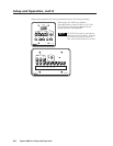
Serial Communication, cont’d
System 5
cc
cc
c
rr
rr
r Plus • Serial Communication4-4
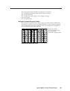
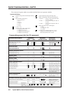
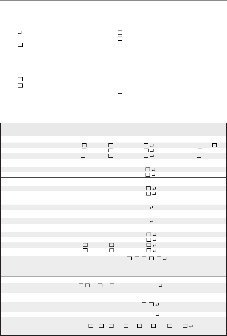
Command/response table for SIS commands
Command description Command Response Additional
ASCII Hex
(switcher to host) description
Input selection
Select both video and audio
X1
! 30 +
X1
21 C
X1
Video & audio input
X1
.
Select audio only
X1
$ 30 +
X1
24 A
X1
Audio input
X1
.
Select video only
X1
& 30 +
X1
26 V
X1
Video input
X1
.
Room function
Turn room function on O 4F Rly
X2
On.
Turn room function off o 6F Rly
X2
Off.
Display (projector) power
Turn display power on [ 5B Pwr
X3
On (discrete).
Turn display power off ] 5D Pwr
X3
Off (discrete).
Display mute
Toggle display mute on/off S/s 53/73 Mut Use S or s to toggle mute.
Display mode
Toggle display mode J 4A Mde
Audio gain/attenuation
Increase audio gain {G 7B 47 Aud
X4
Increment up (amp output).
Decrease audio gain }G 7D 47 Aud
X4
Increment down (amp out.).
Set amp output gain 0*
X4
G 30 2A
X4
47 Aud
X4
Affects master output volume.
Set input attenuation 1*
X4
G 31 2A
X4
47 Aud
X4
Adjusts the active input’s gain.
Read attenuators *A 2A 41
X4
•
X4
•
X4
•
X4
•
X4
Displays the attenuation
status for audio inputs PC 1,
PC 2, Input 3, Vid 1, and
Vid 2, in that order.
Video configuration
Set video signal type
X5
*
X6
\
X5
2A
X6
5C Vid/Y-C/RGB Set signal type for Input 3,
Vid 1, or Vid 2.
Firmware version, part number, & information requests
Query firmware version number Q/q 51/71 Ver
X7
•
X7
Display controller and
IR firmware version.
Request part number N/n 4E/6E N60-269-02 Display switcher’s part #.
Request information Command = I/i 49/69 (see below) Display status.
Response = V
X1
•A
X1
•T
X6
•Pwr
X3
•Rly
X2
•Clp
X2
• Amt
X2
•Aud
X4
Note: Amt is audio mute.
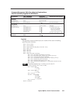
The command/response tables use symbols (defined below) to represent variables.
X4
= Audio attenuation steps (0 through 100)
X5
= Which configurable video input (3 through 5)
3= Input 3 ....... Input 3 can be composite video,
S-video, or RGB.
4 = Vid 1 .......... Vid 1 can be composite video or
S-video.
5 = Vid 2 .......... Vid 2 can be composite video or
S-video.
X6
= Video input signal type (0 through 2)
0 = RGB
1 = composite video
2 = S-video
X7
= Switcher main controller firmware version
(listed to two decimal places e.g.: x.xx),
followed by IR firmware version
Symbol definitions
= CR/LF (carriage return/line feed) (hex 0D 0A)
• = Space
X1
= Input number (0 through 5)
0 = no connection
1 = PC 1
2 = PC 2
3 = Input 3
4 = Vid 1
5 = Vid 2
X2
= 0 = off, 1 = on
X3
= Display power status (0 through 3)
0 = display power is off
1 = display power is on
2 = display is powering down
3 = display is powering up