


4-5System 5
cc
cc
c
rr
rr
r Plus • Serial Communication
Flag block
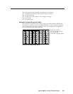
The flag block consists of fifteen bytes (0 to 14) that will be used for handling
special operation functions.
Byte 0 – Power on delay
Byte 1 – Power off delay
Byte 2 – Triple-action switching delay (0.5 second * value)
Byte 3 – Relay control
Byte 4 – Not used
Byte 5 – Not used
Byte 6 – Not used
Byte 7 – Mute control and various flags
Bit 7 – true = mute audio upon display power-down
Bit 6 – true = limit initial system volume (upon switcher power-up)
Bit 5 – true = send responses to RS-232 commands
Bit 4 – true = send channel change IR command upon display power-up
Bit 3 – false = disable front panel volume knob
Bit 2 – false = disable IR while display power is off
Bit 1 – false = fixed Line Out output level (1 = volume knob controls Line Out)
Bit 0 – unused
The factory default for byte 7 is all bits set to On (hex FF).
Byte 8 – Video type (composite video, S-video, or RGB)
Bit 5 = video 5 mode
0 = video
1 = S-video
Bit 4 = video 4 mode
0 = video
1 = S-video
Bit 3 = reserved
Bits 2 & 1 = video 3 mode
00 = RGB
01 = S-video
10 = video
11 = undefined
Bit 0 = reserved
Byte 14 – Checksum
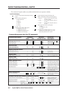
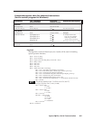
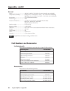
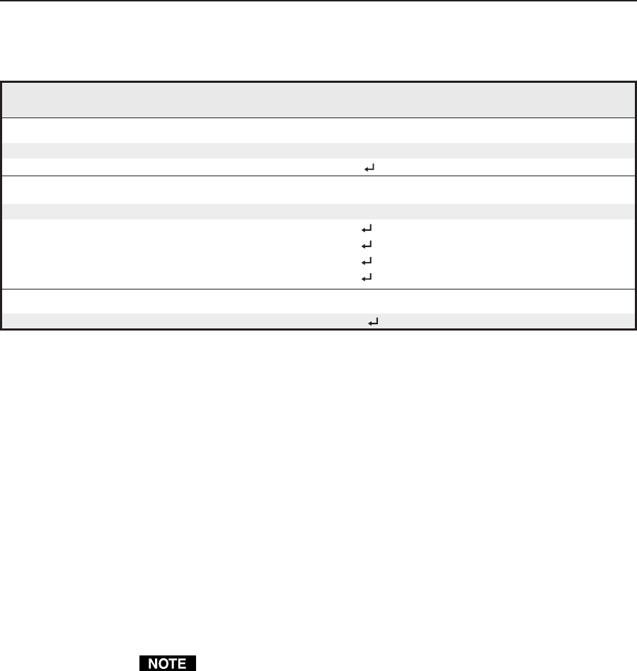
Command/response table for advanced instructions
(for the control program for Windows)
Command Hex. command Response Additional description
(host to switcher) (switcher to host)
IR block
Read (upload) 80 83 8k bytes of data
Write (download) 80 82 [8 kbytes] Dnl Downloads 8 kbytes.
Flag block
Read (upload) 80 85 15 bytes of data
Write (download) [Byte0]*[Byte1] 91 Flg
[Byte2]*[Byte3] 93 Flg
[Byte6]*[Byte7] 97 Flg
[Byte8]* 30 99 Flg
Unit reset
Reset unit 80 81 Upd
Example:
To set byte 0 to 21 and
byte 1 to 100, send the
following command:
30 32 31 2A 31 30 30 91
hex
The byte value range is 0-255.