


2-5System 5
cc
cc
c
rr
rr
r Plus • Installation
This output provides 24 watts of power (12 watts per channel with a 4 ohm
load) or 12 watts ( 6 watts per channel with an 8 ohm load). The output level
varies depending on the front panel volume adjustment.
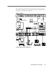
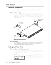
Control device connections
Captive screw and 3.5 mm stereo jack connectors are included with the
System 5, but the installer provides the cables.
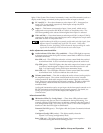
RS-232
L
R
L
R
AUX 1 AUX 2
AMPLIFIED OUT
DISPLAY PWR
SENSOR
RELAY COMM.
A
B
C
D
E
2 431 5
1
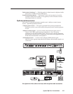
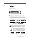
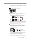
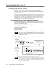
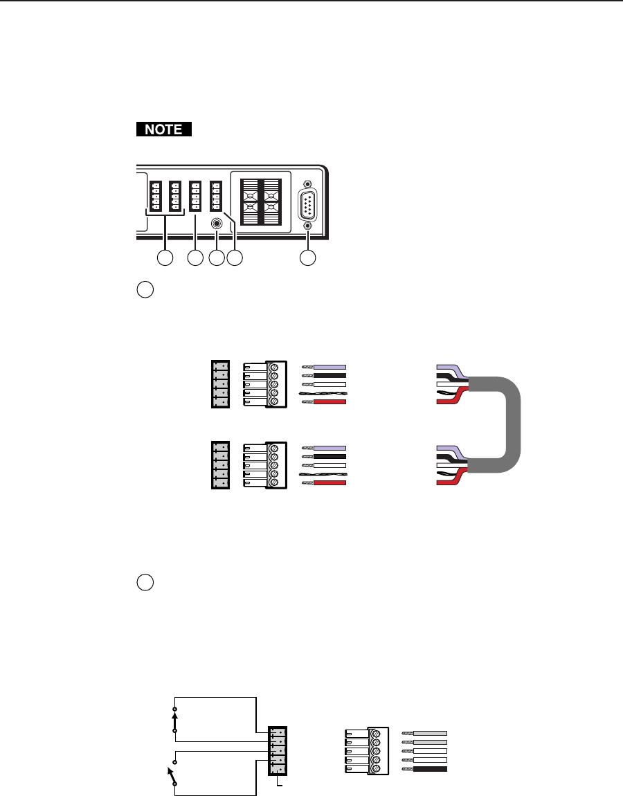
Auxiliary outputs (Aux 1, Aux 2) — One optional external SCP 100P,
SCP 250, or SCP/AAP A control panel can be connected to each of these
5-pole captive screw connectors. The control panel replicates the switcher’s
front panel control features. Wire the connectors as shown below.
IR signals in (violet)
Gnd (black)
Gnd (drain)
+12V (red)
System 5
AUX port
AUX
A
B
C
D
E
A
B
C
D
E
Comm signal (white)
IR signals in (violet)
Gnd (black)
Gnd (drain)
+12V (red)
Comm signal (white)
Port on
SCP
circuit
board
The Aux 1 and Aux 2 ports provide a total of 500 mA, split between the two
ports, so each port provides 250 mA of current. Refer to the SCP 100P User’s
Manual (part #68-390-01) or the SCP/AAP A, SCP 200, SCP 250 User’s Manual
(part #68-511-01) for details about the control panels.
2
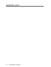
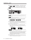
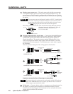
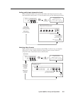
Room/relay port (Relay) — This allows control of “room” functions – items
such as room lighting, window coverings, and display screens – via
momentary or latching contact. These contacts can be used to control any
equipment as long as the contact specifications of a total of 24 volts at
1 ampere are not exceeded.
This port has two sets of contacts: one pair is closed by default, the other pair
is open by default, as shown below.
Normally closed (2)
Normally closed (1)
Normally open (2)
Normally open (1)
Not
used
System 5
RELAY port
To / from
room control
equipment
Normally closed (2)
Normally closed (1)
Normally open (2)
Normally open (1)
Not used
When the room function is active, the closed contacts open, and the open
contacts close. Contacts can be programmed to operate in one of two ways:
• latching (brief contact) (press to turn on, press to turn off), or
• momentary (timed) (press to turn on, timeout to turn off).
In the timed mode the default timeout period is 1/8 second. Use the control
software for Windows to change the length of the timeout period. See Serial
Communications, chapter 4, for details.