


Installation, cont’d
System 5
cc
cc
c
rr
rr
r Plus • Installation2-4
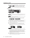
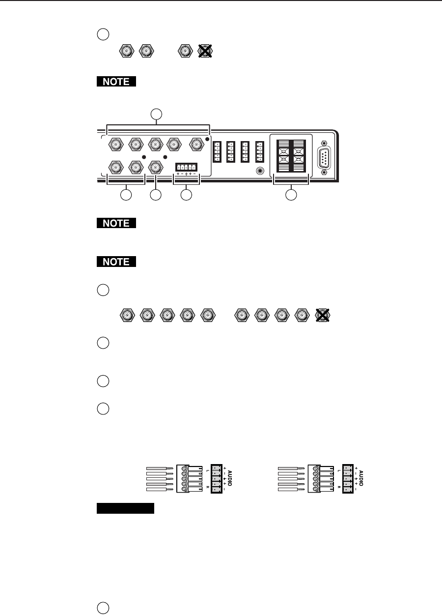
RS-232
RGB
H/HV
V
Y
C VID
LINE OUT
L
L
R
R
L
R
AUX 1 AUX 2
AMPLIFIED OUT
DISPLAY PWR
SENSOR
RELAY COMM.
A
B
C
D
E
O
U
T
P
U
T
S
3
1
2 54
4
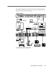
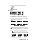
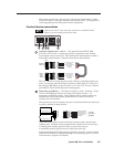
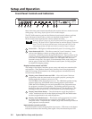
Vid 1 and Vid 2 composite/S-video inputs — Connect the cables as shown
here. For S-video, connect the luma (Y) signal to
the left BNC connector, marked V/Y, and the
chroma signal (C) to the right BNC, marked C.
Configure the video format via the front panel or using RS-232 programming.
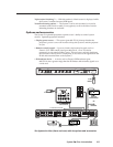
Outputs
All three outputs can be connected simultaneously, although only one is active
at a time. The output that is active is determined by the format of the active
input.
The LED next to the connector(s) for each output (RGB, S-video, or composite
video) lights when that output is active.
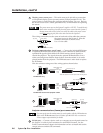
1
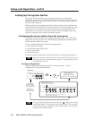
RGB output BNC connectors — Connect coaxial cables from the display
device to these BNCs for one RGBHV or RGBS video output as follows:
RGB
H/HV
V
RGBS
RGB
H/HV
V
RGBHV
2
S-video output (Y, C) — For S-video output, connect the cable for the luma (Y)
signal to the Y connector, and the cable for chroma (C) signal to the C
connector. A BNC-to-4-pin mini DIN (S-video) adapter may be required.
3
Composite video output BNC (Vid) — Connect the display device here, via a
coaxial cable, for composite video output.
4
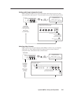
Line level audio output (Line Out) — For unamplified, line level audio
output, connect an audio device, such as an audio recorder or powered
speakers, to this 3.5 mm, 5-pole captive screw connector. Follow the wiring
diagram below.
Unbalanced Output
Tip
See Caution
Sleeve (s)
Tip
See Caution
Balanced Output
Tip
Ring
Sleeve (s)
Tip
Ring
CAUTION
Connect the sleeve to ground (Gnd). Connecting the sleeve to a negative
(-) terminal will damage the audio output circuits.
The signal at this output comes from the selected audio input. The audio level
from the Line Out output can either be variable (in response to front panel
volume adjustment), or it can be set to a fixed level that is not affected by
changes to the front panel volume adjustment. Use the Windows-based
control program to change the output mode setting or to set audio breakaway.
See chapter 4, Serial Communication, for details.
5
Amplified audio output — Connect unpowered speakers directly to these
spring-loaded captive terminals for stereo output. Connect the left channels
to positive/L, and the right channels to negative/R.
V/Y C V/Y C
S-video Composite video