


Setup and Operation, cont’d
System 5
cc
cc
c
rr
rr
r Plus • Setup and Operation3-2
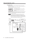
Setup and Operation
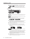
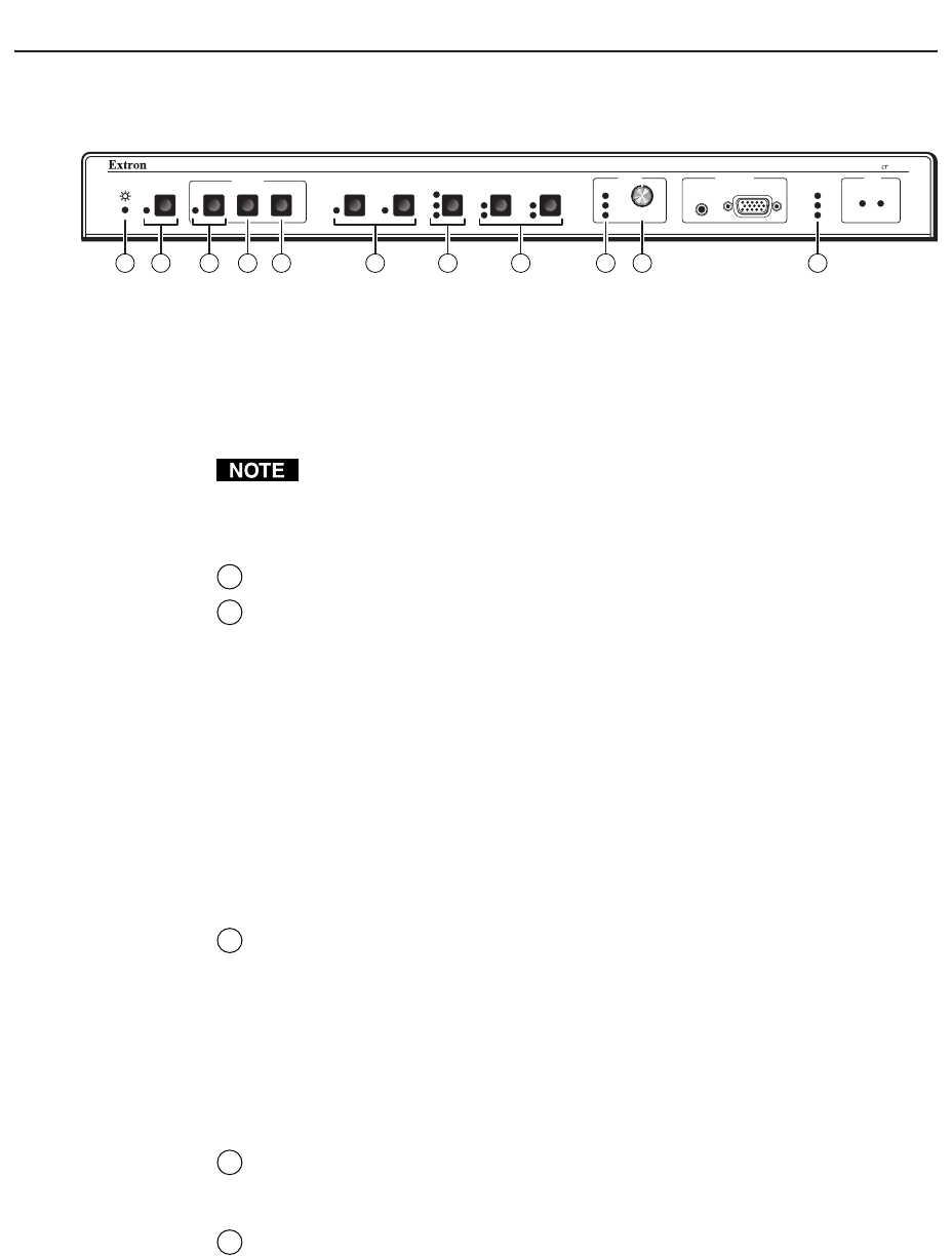
Front Panel Controls and Indicators
VID
MAX.
CLIP
MIN.
TX
RX
IR
LEARN
CONFIG
RETRY
Y/C
VID
PC
Y/C
VID
Y/C
ROOM
DISPLAY
POWER MUTE MODE PC1 PC2 INPUT 3
VOLUME
AUDIO
COMPUTERAUDIO
PC1 INPUT
Plus
SYSTEM 5
VID1 VID2
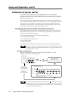
1 4 5 9 10 112 6 83 7
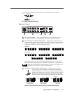
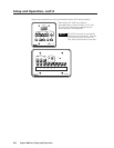
Most of the front panel controls described in this section also have another function
during setup. See Setting Up the System 5
cr
Plus in this chapter.
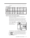
The SCP 100P remote keypad and the Windows-based control software replicate
items 2 through 10 shown above, which are described in this chapter. The
IR 401 remote control replicates the controls without the LEDs.
When the System 5 powers up, all of the front panel LEDs light briefly, then
turn off. The Power LED (1) lights and stays on until the System 5 is powered
down. The LED for the last selected input, and the rear panel LED for the
selected input format will light and remain on until the input is changed.
1
Power LED — This lights to indicate that the System 5 is receiving power.
2
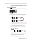
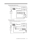
Room button and LED — This allows control of “room” functions – items
such as room lighting, window coverings, and display screens – via
momentary or latching contact through the Relay port. These contacts can be
used to control any equipment as long as the contact specifications of a total
of 24 volts at 1 ampere are not exceeded. The LED lights while the room
function is active (on). See page 2-5 for information on the room/relay port,
and see page 4-7 and refer to the Windows-based System 5cr Help program
for details on changing settings.
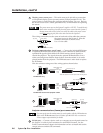
Display function controls and LEDs
The settings of the display functions (power, mute, and mode) are customized for
each projector. These buttons function only after they have been programmed,
either by “learning” IR commands or by loading projector commands (drivers)
from the Extron IR library.
3
Display power (Power) button and LED — Once the System 5 has been
programmed with the commands for the specific projector, pressing this
button toggles the projector’s power on or off.
The LED lights when projector power is on. The LED blinks quickly during
projector power-up, and it blinks slowly during projector power-down.
While the LED is blinking, do not send commands to the projector because
the projector is not able to accept them. The blinking periods (power-up/
down delay time) are generated within the System 5, not the projector. The
blinking periods can be set only via the Windows-based control program.
4
Display mute (Mute) button — Press this button to toggle the projector’s
“mute” function (to turn off/on the displayed image) once the Mute button
has been programmed for use with the projector.
5
Display mode (Mode) button — This button can be programmed to switch
the mode of the projector between computer-video (RGB), S-video, and
composite video. It replicates the 1-button (step) mode function provided on
some projectors’ remote controls.
Input selection controls and LEDs
Use these buttons to select the appropriate input source. LEDs next to each button
indicate the format of the incoming video signal. Only the selected input’s LED