


MMX 32 VGA MTP • Installation and Operation 5
Furniture Mounting
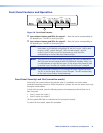
Use the optional MBU 125 mounting kit (part number 70-077-01) to mount the MMX as
follows:
1. Remove the feet from the bottom of the MMX, if installed.
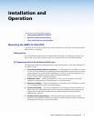
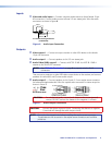
2. Attach the mounting brackets to the MMX with the provided machine screws
(figure 4).
Figure 4. Mounting the MMX 32 VGA MTP Under Furniture
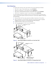
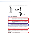
3. Hold the device with the attached brackets against the underside of the mounting
surface. Mark the bracket screw hole locations on the mounting surface.
4. Drill 3/32 inch (2 mm) diameter pilot holes, 1/4 inch (6.3 mm) deep in the mounting
surface at the marked locations.
5. Insert #8 wood screws into the pilot holes. Tighten the screws until just less than
1/4 inches of the head protrudes.
6. Align the mounting screws with the slots in the brackets and place the MMX against the
surface, with the screws through the bracket slots.
7. Slide the device slightly forward or back, then tighten all four screws to secure it in
place.
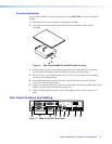
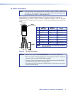
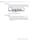
Rear Panel Features and Cabling
INPUT 2
INPUT 1
AUDIO
AUDIO
OUTPUT 1
LR
AUDIO
INPUT 3
AUDIO
AUDIO
POWER
12V
0.5A MAX
REMOTE
RS-232
+5V
2
1
1 2 3
Tx Rx
SYNC - TRI
PRE PEAK - ON
OUTPUT 2
RGB/AUDIO
CONTACT
9
1
2
3
4
6
5
7 8
BI
OFF
Figure 5. MMX 32 VGA MTP Rear Panel