


MMX 32 VGA MTP • Installation and Operation 6
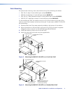
Inputs
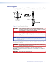
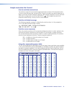
a Video and audio inputs — Connect computer video sources to these female 15-pin
HD connectors. Connect audio sources to these 3.5 mm stereo jacks. Wire the audio
connectors as shown in figure 6.
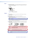
Sleeve ( )
Ring (R)
Tip (L)
3.5 mm Stereo Plug Connector
(unbalanced)
Figure 6. Audio Input Connection
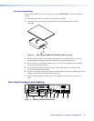
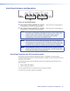
Outputs
b Video output 1 — Connect an output monitor or other VGA device to this female
15-pin HD connector.
c Audio output 1 — Connect speakers to this 3.5 mm stereo jack.
d Audio/Video (RGB) output 2 — Connect an MTP R 15 HD A or MTP RL 15HD A
receiver to this RJ-45 UTP connector.
NOTE: See “TP Cable Termination” on page 9 to properly wire the RJ-45
connectors.
Then connect a projector or other RGB video output device to the receiver, and connect
speakers for summed (L and R) mono audio output.
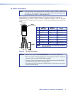
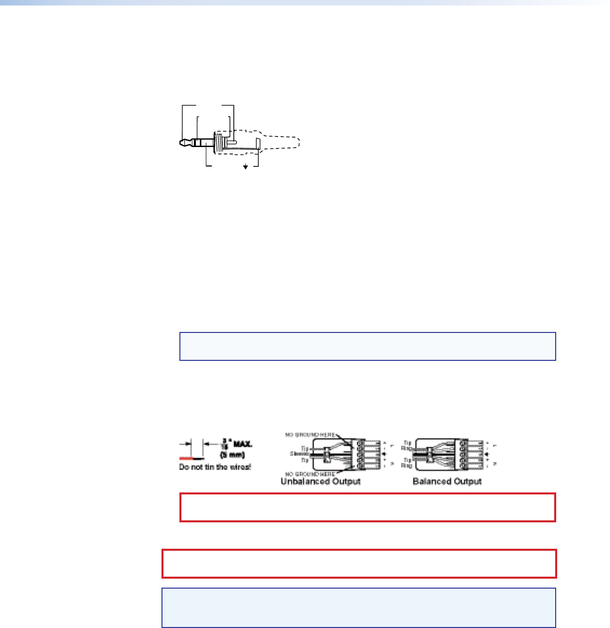
e Audio output 2 — Connect speakers to this 5-pole, 3.5 mm captive screw connector
for balanced/unbalanced audio. Wire the captive screw connector for stereo output as
shown in figure 7.
Figure 7. Audio Output Connections
CAUTION: Connect the sleeve to ground (Gnd). Connecting the sleeve to a negative
(-) terminal will damage the audio output circuits.
NOTE: Do not tin the stripped wires before installing the captive screw connector.
Tinned wires are not as secure in the captive screw connectors and could be
pulled out.
CAUTION: For unbalanced audio, connect both sleeves to the center (ground)
contact. DO NOT connect the sleeves to the negative (-) contacts.