


MMX 32 VGA MTP • Installation and Operation 10
Front Panel Features and Operation
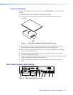
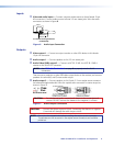
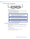
MMX 32 VGA MTP
OUTPUT 1
213
OUTPUT 2
213
1
2
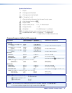
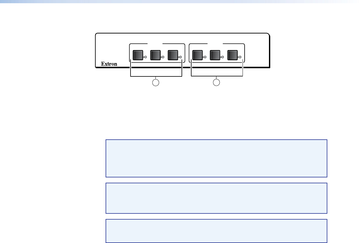
Figure 10. Front Panel Features
a Input selector buttons and LEDs for output 1 — Press the button corresponding to
the desired input. The LED for that input lights.
b Input selector buttons and LEDs for output 2 — Press the button corresponding to
the desired input. The LED for that input lights.
NOTE: When power is applied, the LEDs light sequentially from left to right. For first
time power up, the default configuration of the unit is input 1 tied to both
outputs 1 and 2, so that the input 1 LEDs for both output 1 and for
output 2 are lit. If this is not a first time power up, then the LEDs
corresponding to the last valid input selections light.
NOTE: Tying input 0 to an output is done only using RS-232, and it is reflected on
the front panel and any optional MMX 32 AAP/MAAP installed. When a tie
is made between an input and an output, if that output was previously tied
to another input, the older tie is broken when the new input is selected.
NOTE: Audio breakaway is done by RS-232 through the Extron Simple Instruction
Set (SIS) or the Universal Switcher Control Program. The LED corresponding
to the audio source flashes during breakaway.
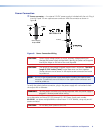
Front Panel Security Lock Out (executive mode)
Locking the front panel protects the switcher when it is installed in a location where
unwanted tampering may occur. While the switcher is locked, the user can select inputs only
through a remote device.
To lock the front panel, press the following buttons simultaneously and hold them for at
least 3 seconds:
• Input 1 button for output 1
• Input 3 button for output 2
The front panel LEDs flash to indicate that the front panel is locked.
To unlock the front panel, repeat this procedure.