


FS-8700-49_Data_Aire_DAP Page 4 of 48
FieldServer Technologies 1991 Tarob Court Milpitas, California 95035 USA Web:www.FieldServer.com
Tel: (408) 262-2299 Fax: (408) 262-2269 Toll_Free: 888-509-1970 email: support@FieldServer.com
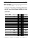
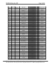
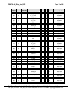
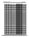
1. Data Aire Description
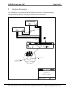
The Data Aire Driver is capable of direct connection to a network of Data Aire DAP devices.
The FieldServer is connected in a RS-485 loop topology. Two FieldServer ports are required
per loop. The driver is an active client. All data is obtained by poll & response.
Connection to a DART is not supported by this driver.
The driver may be configured very simply (See Section 4.4). A number of advanced
configurations are also available and are described in Appendix B. The driver supports the
common message formats for common Data Aire DAP devices. A list of the supported
messages is provided in the manual.
The information that follows describes how to expand upon the factory defaults provided in the
configuration files included with the FieldServer.
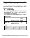
1.1. Performance Issues - DARTIII only
Data Aire communication is based on a very low baud rate. In addition inter-message timing
constraints and overhead requirements for active messages in a Dart configuration add
significant time to each transaction. It is not possible to write a setpoint to a device until the
device has been successfully read, and the result of the write will not be seen until the next
read is complete. The result of a write may not be seen for some time due to slow
communications and significant inter poll delays.
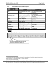
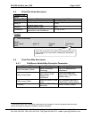
1.2. Data Alarm Network Module Network LED Operation
DAP-II units communicate with a DART unit by using a Data Alarm Network Module. This
module provides a RS-485 communications link. Installed on the card are several LEDS.
The table below explains how the LEDS appear under normal (correctly functioning)
operation.
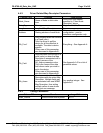
LED LED Appearance
FUSE
The Network Module has a blown fuse detection circuit. If one (or more) of
the fuses has an open circuit, then the FUSE LED will be lit. Normally, this
LED is dark.
DS1 &
DS3
Communications signals enter and leave the Network Module. These LEDS
reflect the communications activity. When first powered up, both LED's will
be lit and the illumination will be steady. As the DART communicates with
the network, both LED’s will begin to flicker in unison. All of the Network
Module LED’s will flicker at the same time.
NETWORK
At some point the DART will send a communication message to a specific
network-connected DAP-II that requires a reply to the DART. If the message
is received without error, the DAP-II will reply by engaging a relay on the
Network Module and transmitting a message. When this happens the
NETWORK LED will come on. Whenever a NETWORK LED is seen to
come on it means that the communications into the Network Module is
satisfactory. It is still possible to have a wiring problem downstream of the
module that prevents the message from being received by the DART