


Using DSP-LINK
Preparing for Data Transfer
A
A-3
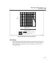
12345678
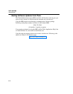
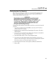
PC Rear Panel (Typical)
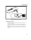
Use the 9-pin to 25-pin
adapter if necessary.
gc41f.eps
Figure A-1. Connecting the Test Tool to a PC
Configuring the Serial Ports
Transferring data requires the serial ports on the test tool and the PC to have the
same interface configurations.
You can view or change the test tool’s serial port configuration in the SETUP
mode. For complete instructions, refer to Chapter 5, “Viewing and Printing Saved
Reports.”
The DSP-LINK software allows you to configure a PC’s serial port. The PC serial
port configuration includes baud rate, flow control protocol, and a port number
selection.