


DSP-100/2000
Users Manual
3-10
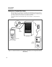
Attenuation
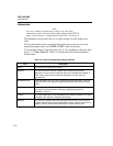
Note
Incorrect conduit or temperature settings can cause false
attenuation results. You can change these settings in the SETUP
mode, as described in “Configuring the Test Tool” in Chapter 2.
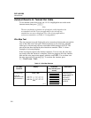
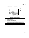
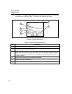
The attenuation test measures the loss of signal strength over the length of the
cable.
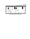
The first attenuation results screen shows the cable pairs tested, the worst-case
attenuation margin found, and a PASS or FAIL result for each pair.
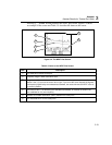
To see detailed results for the cable pairs, use D U to highlight a cable pair, then
press @ View Result. Table 3-2 describes the items on the attenuation
results screen.
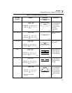
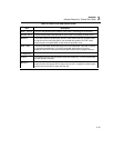
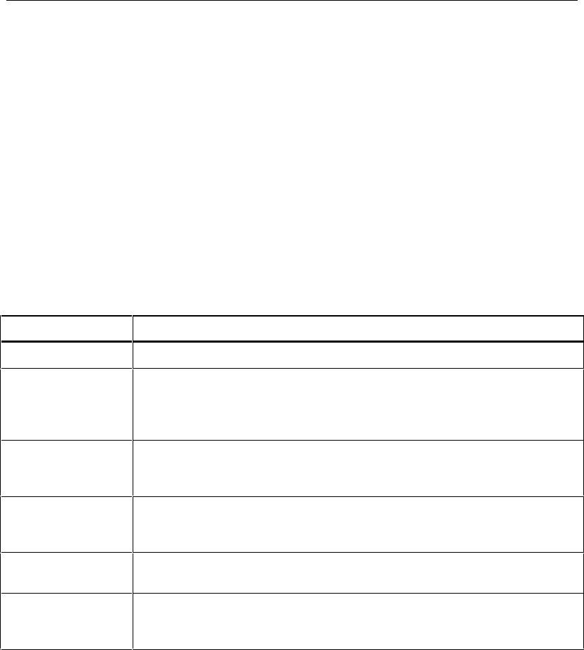
Table 3-2. Items on the Attenuation Results Screen
Item Description
Pair
The cable pair relevant to the results.
Result
The overall result for the test. A PASS result means that measured
attenuation is lower than the specified limit for the selected test standard. A
FAIL result means that the measured attenuation is higher than the
specified limit.
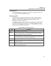
Attenuation If the test passed, this value is the highest measured attenuation. If the test
failed, this value is the highest measured attenuation that exceeds the test
limits.
Frequency
If the test passed, this frequency is where the highest measured attenuation
occurred. If the test failed, this is where the highest failing value of
attenuation occurred.
Limit
The highest attenuation value acceptable at the frequency shown. This value
is based on the maximum allowable cable length.
Margin
The difference between the worst-case attenuation and the limit. A positive
number means that the measured attenuation value is lower than the limit. A
negative number means that the attenuation is higher than the limit.