


Manual Supplement DSP-100,DSP2000 Users
7/002
Change #2
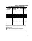
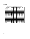
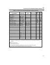
On pages 3-6 and 3-7, replace Table 3-1 with the following:
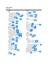
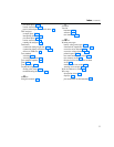
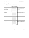
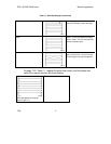
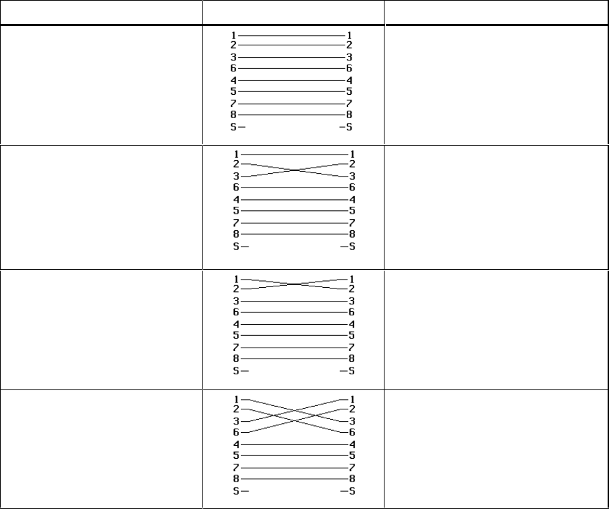
Table 3-1. Wire Map Displays
Wire Map Condition Displayed Schematic Description
Correct wiring
(Left side of display represents
near-end connector.)
gc43i.eps
Cable wiring is correct. Shield(sS)
shown only if required by selected
test standard.
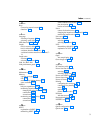
Crossed wires
gc45i.eps
A wire in the 1,2 pair is crossed with a
wire in the 3,6 pair.
Reversed pairs
gc47i.eps
Wires 1 and 2 are crossed.
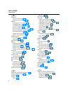
Transposed pairs
gc49i.eps
The wire pair connected to pins 1 & 2
at one end is connected to pins 3 & 6
at the other end.