


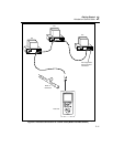


Getting Started
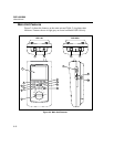
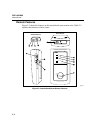
Remote Features
2
2-15
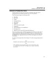
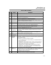
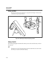
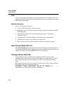
Table 2-5. Remote Connectors and Features
Item Feature Description
1
RS-232C serial
port
A DB9P connector for loading software updates.
2
AC adapter/
charger jack
Connection for the ac adapter/charger supplied with the test tool.
3
AC power
indicator
LED Style 1: A green LED that turns on when the test tool is powered
with the ac adapter/charger.
LED Style 2: A multicolor LED with four states:
Off: AC adapter/charger is not connected, or is connected without
the battery pack installed.
Blinking Red: The ac adapter/charger is trickle charging the battery
in preparation for fast charging. This mode indicates an extremely
low battery voltage. The test tool may not operate.
Steady Red: The ac adapter/charger is fast charging the battery.
Steady Green: Fast charging is complete. The ac adapter/charger
continues to trickle charge the battery.
4
RJ45 connector A shielded 8-pin jack for shielded and unshielded twisted pair cable.
5
Pass LED A green LED that turns on at the end of a test if no faults were
detected.
6
Test LED A yellow LED that turns on when a test is in progress.
7
Fail LED A red LED that turns on at the end of a test if one or more faults were
detected.
8
Low-battery LED A LED that turns on when the smart remote battery voltage is low.
9
Rotary switch On/off switch for smart remote.