


vii
List of Figures
Figure Page
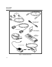
1-1. Standard Accessories .................................................................................. 1-4
2-1. The Asterisk and Test Tool Accuracy ........................................................ 2-6
2-2. Autotest Connections for Twisted Pair Cable (Channel) ........................... 2-8
2-3. Autotest Connections for Coaxial Cable .................................................... 2-11
2-4. Main Unit Features ..................................................................................... 2-12
2-5. Standard and Smart Remote Features......................................................... 2-14
2-6. Attaching the Strap and Opening the Bail .................................................. 2-16
3-1. Autotest Connections for Twisted Pair Cable (Basic Link) ....................... 3-2
3-2. Examples of Automatic Diagnostics Displays............................................ 3-5
3-3. The Attenuation Plot Screen....................................................................... 3-11
3-4. The NEXT Plot Screen ............................................................................... 3-13
3-5. The ACR Plot Screen.................................................................................. 3-16
3-6. The RL Plot Screen..................................................................................... 3-18
3-7. Autotest Connections for Coaxial Cable .................................................... 3-21
3-8. Screen for Saving Autotest Results ............................................................ 3-24
3-9. Part of an Autotest Report for Twisted Pair ............................................... 3-26
3-10. Autotest Report for Coaxial Cable ............................................................. 3-27
3-11. Autotest Report Summary........................................................................... 3-27
4-1. Single Test Connections for Twisted Pair Cable........................................ 4-4
4-3. Example of a TDX Analyzer Plot for a Good Twisted Pair Cable Run..... 4-8
4-3. Example of a TDR Plot (Twisted Pair Results).......................................... 4-12
4-4. Single Test Connections for Coaxial Cable................................................ 4-15
4-5. Connections for Monitoring Network Traffic ............................................ 4-17
4-6. Connections for Monitoring Impulse Noise ............................................... 4-21
5-1. Connections for Printing Test Reports ....................................................... 5-3
6-1. Connections for Self-Calibration (Smart Remote Shown) ......................... 6-2
7-1. Twisted Pair Cable Construction................................................................ 7-2
7-2. EIA/TIA RJ45 Connections........................................................................ 7-3
7-3. Coaxial Cable Construction........................................................................ 7-4
7-4. Attenuation of a Signal ............................................................................... 7-5
7-5. Sources of Electrical Noise......................................................................... 7-6