


MOTOROLA Chapter 6. Programming Model 6-1
PRELIMINARYÑSUBJECT TO CHANGE WITHOUT NOTICE
Chapter 6
Programming Model
60
60
This chapter gives an overview of the MPC860T implementation of the Fast Ethernet
controller (FEC) registers, buffer descriptors (BDs), and initialization.
6.1 Overview
The FEC software model is similar to that used by the 10-Mbps Ethernet implemented on
the MPC860 core device. To support higher data rates, the FEC has a different internal
architecture, which changes the programming model slightly. However, efforts have been
taken to minimize the differences required by the interrupt handlers. The FECÕs registers
are very different from those of the CPM-based internal Ethernet controller.
The FEC is programmed by a combination of control/status registers (CSRs) and BDs. The
CSRs are used for mode control and to extract global status information. The BDs are used
to pass data buffers and related buffer information between hardware and software.
Some registers are located in on-chip RAM. All on-chip registers, whether located in RAM
or in hardware, must be accessed using big-endian mode, therefore, descriptions in this
chapter assume big-endian byte ordering. There is no support for little-endian in the FEC.
6.2 Parameter RAM
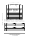
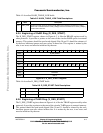
Table 6-1 brießy describes each enter in the FEC parameter RAM.
Table 6-1. FEC Parameter RAM Memory Map
Address Name Description Section
0xE00 ADDR_LOW Lower 32 bits of address 6.2.1
0xE04 ADDR_HIGH Upper 16 bits of address 6.2.2
0xE08 HASH_TABLE_HIGH Upper 32 bits of hash table 6.2.3
0xE0C HASH_TABLE_LOW Lower 32 bits of hash table 6.2.4
0xE10 R_DES_START Pointer to beginning of RxBD ring 6.2.5
0xE14 X_DES_START Pointer to beginning of TxBD ring 6.2.6
0xE18 R_BUFF_SIZE Receive buffer size 6.2.7
Fr
eescale S
emiconduct
or
, I
Freescale Semiconductor, Inc.
For More Information On This Product,
Go to: www.freescale.com
nc...