


7-2 MPC860T (Rev. D) Fast Ethernet Controller Supplement MOTOROLA
PRELIMINARYÑSUBJECT TO CHANGE WITHOUT NOTICE
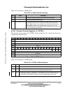
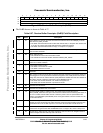
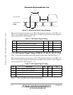
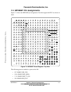
Figure 7-1. MII Receive Signal Timing Diagram
The receiver functions correctly up to a RX_CLK maximum frequency of 25 MHz +1%.
There is no minimum frequency requirement. In addition, the processor clock frequency
must exceed the RX_CLK frequency - 1%.
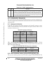
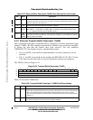
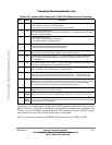
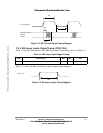
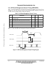
7.3.2 MII Transmit Signal Timing (TXD[3:0], TX_EN, TX_ER, TX_CLK)
Table 7-2 provides information on the MII transmit signal timing, shown in Figure 7-2.
The transmitter functions correctly up to a TX_CLK maximum frequency of 25 MHz +1%.
There is no minimum frequency requirement. In addition, the processor clock frequency
must exceed the TX_CLK frequency - 1%.
Figure 7-2 shows the MII transmit signal timing diagram.
Table 7-1. MII Receive Signal Timing
Num Characteristic Min Max Unit
M1 RXD[3:0], RX_DV, RX_ERR to RX_CLK setup 5 Ñ ns
M2 RX_CLK to RXD[3:0], RX_DV, RX_ERR hold 5 Ñ ns
M3 RX_CLK pulse width high 35% 65% RX_CLK period
M4 RX_CLK pulse width low 35% 65% RX_CLK period
Table 7-2. MII Transmit Signal Timing
Num Characteristic Min Max Unit
M5 TX_CLK to TXD[3:0], TX_EN, TX_ER invalid 5 Ñ ns
M6 TX_CLK to TXD[3:0], TX_EN, TX_ER valid Ñ 25
M7 TX_CLK pulse width high 35% 65% TX_CLK period
M8 TX_CLK pulse width low 35% 65% TX_CLK period
M1
M2
RX_CLK (input)
RXD[3:0] (inputs)
RX_DV
RX_ER
M3
M4
Fr
eescale S
emiconduct
or
, I
Freescale Semiconductor, Inc.
For More Information On This Product,
Go to: www.freescale.com
nc...