


MOTOROLA Chapter 7. Electrical Characteristics 7-1
PRELIMINARYÑSUBJECT TO CHANGE WITHOUT NOTICE
Chapter 7
Electrical Characteristics
70
10
This chapter contains detailed information on DC and AC electrical characteristics and AC
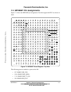
timing speciÞcations for the MPC860T MII signals and a MPC860T pinout diagram. For
information on maximum ratings, thermal characteristics, power considerations, and layout
practices, see the MPC860 PowerQUICC Hardware SpeciÞcations.
Note: These preliminary speciÞcations are based on design simulations. Finalized
speciÞcations will be made available after characterization and device qualiÞcations are
completed.
7.1 DC Electrical Characteristics
MPC860T DC electrical characteristics are identical to those of the MPC860. The MII
output signals that are new on the MPC860T all have an IOL of 3.2 mA.
7.2 AC Electrical Characteristics
The timing speciÞcations for the MPC860T MII signals are independent of system clock
frequency (part speed designation).
7.3 Electrical SpeciÞcations
MII signals use TTL signal levels compatible with devices operating at either 5.0 V or 3.3 V.
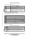
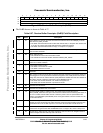
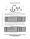
7.3.1 MII Receive Signal Timing (RXD[3:0], RX_DV, RX_ER, RX_CLK)
Table 7-1 provides information on the MII receive signal timing, shown in Figure 7-1.
Fr
eescale S
emiconduct
or
, I
Freescale Semiconductor, Inc.
For More Information On This Product,
Go to: www.freescale.com
nc...