


MOTOROLA Chapter 7. Electrical Characteristics 7-3
PRELIMINARYÑSUBJECT TO CHANGE WITHOUT NOTICE
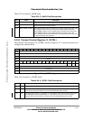
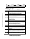
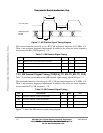
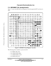
Figure 7-2. MII Transmit Signal Timing Diagram
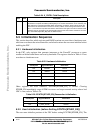
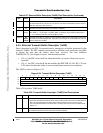
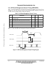
7.3.3 MII Async Inputs Signal Timing (CRS, COL)
Table 7-3 provides information on the MII async inputs signal timing, shown in Figure 7-3.
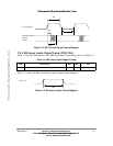
Figure 7-3 shows the MII asynchronous inputs signal timing diagram.
Figure 7-3. MII Async Inputs Timing Diagram
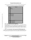
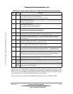
Table 7-3. MII Async Inputs Signal Timing
Num Characteristic Min Max Unit
M9 CRS, COL minimum pulse width 1.5 Ñ TX_CLK period
M6
TX_CLK (input)
TXD[3:0] (outputs)
TX_EN
TX_ER
M5
M7
M8
CRS, COL
M9
Fr
eescale S
emiconduct
or
, I
Freescale Semiconductor, Inc.
For More Information On This Product,
Go to: www.freescale.com
nc...