


Chapter 1 Preparations
IP-9610
7
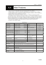
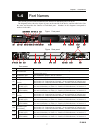
1.4 Part Names
This section gives the name and describes the function of individual parts of IP-9610.
The diagrams below show the layout of parts on the outside of the device, and the table below lists
the name and describes the function of individual parts. Numbers in the diagrams correspond to
numbers in the table.
Figure Front panel
Figure Rear panel
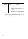
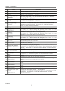
Part names
No. Name Description
(1)
SD CARD slot
For maintenance purpose. Not for customer. (Future Support)
Covered with screw.
(2)
Maintenance port
For maintenance purpose. Not for customer..
(3)
USB port
For maintenance purpose. Not for customer. (Future Support)
(4)
LAN port #1
(LAN1)
Ethernet 10BASE-T/100BASE-TX /1000BASE-T communication port.
See Section 2.6, “Connection to a Network,” for an explanation on using this port.
See Section 4.2, “Cable and Connector Details,” for cable connection information.
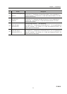
(5)
Status LED
(LINK/ACT)
Indicates the status of LAN port.
For more information, see Table 5.3, “Details of LED Indications,” in Section 5.2.
(6)
Speed LED
(100/1000M)
Indicates the speed of LAN port.
For more information, see Table 5.3, “Details of LED Indications,” in Section 5.2.
(7)
LAN port #2
(LAN2)
Ethernet 10BASE-T/100BASE-TX /1000BASE-T communication port.
See Section 2.6, “Connection to a Network,” for an explanation on using this port.
See Section 4.2, “Cable and Connector Details,” for cable connection information.
(8)
Status LED
(LINK/ACT)
Indicates the status of LAN port.
For more information, see Table 5.3, “Details of LED Indications,” in Section 5.2.
(9)
Speed LED
(100/1000M)
Indicates the speed of LAN port.
For more information, see Table 5.3, “Details of LED Indications,” in Section 5.2.
(10)
CONSOLE port
(CONSOLE)
Ethernet 10BASE-T/100BASE-TX /1000BASE-T communication port
.
See Section 2.6, “Connection to a Network,” for an explanation on using this port.
See Section 4.2, “Cable and Connector Details,” for cable connection information.
(11)
Status LED
(LINK/ACT)
Indicates the status of console port.
For more information, see Table 5.3, “Details of LED Indications,” in Section 5.2.
(12)
Speed LED
(100/1000M)
Indicates the speed of console port.
For more information, see Table 5.3, “Details of LED Indications,” in Section 5.2.
1
2
3
4
1.4