


Chapter 1 Preparations
IP-9610
8
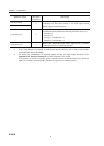
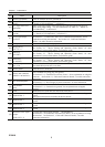
No. Names Description
(13)
Power LED (PWR)
Turns on when the device is powered on.
(14)
Status LED
(RDY)
Turn on when IP-9610 power is on. For more information, see Table 5.3,
“Details of LED Indications,” in Section 5.2.
(15)
AV input status LED
(INDWN)
Audio/Video input setting status indicator and LED that indicates the input off
status during input setting. For more information, see Table 5.3, “Details of
LED Indications,” in Section 5.2.
(16)
Alarm LED
(ALM)
Turns on when IP-9610 operation is abnormal. For more information, see Table
5.3, “Details of LED Indications,” in Section 5.2.
(17)
Voice input/output
(VOICE)
Voice communication (Intercom) port between IP-9610s.
See Section 2.7, “Connection to the Voice Communication (Intercom)” for an
explanation on using this terminal. See Section 4.2, “Cable and Connector
Details,” for cable connection information.
(18) VFD panel
Uses to set IP-9610 up and displays status. 4 lines x 24 characters.
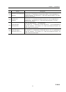
(19)
Direction key
(△▽Y Z)
Uses to operate IP-9610 and check the status.
See Section 3.3, “Device Setting and Operation (Front Panel)” for more
explanation.
For more information, see Software guide.
(20)
Enter key
(ENTER)
Used to finalize the displayed data on the front panel.
See Section 3.3, “Device Setting and Operation (Front Panel)” for more
explanation.
For more information, see Software guide.
(21)
Cancel key
(CANCEL)
Used to cancel the displayed data on the front panel.
See Section 3.3, “Device Setting and Operation (Front Panel)” for more
explanation.
For more information, see Software guide.
(22)
Function key
(F1~F4)
Short cut key for VFD operation. Please refer “Software User’s Guide” for
more detail description how to use them.
(23)
Power button
Turns the device on and off.
(24)
Power inlet connector
(INPUT 100-240VAC)
Can be connected to a 100-240VAC commercial power supply by using power card
with a standard two-prong plug with ground.
See Section 2.2.2, “Connection to a Power Source,” for an explanation on using this
connector. See Section 4.2, “Cable and Connector Details,” for cable connection
information.
(25)
AC cord clamp hole
Hole to fix AC cord clamp.
See Section 2.2.2, “Power Supply System Connection” for more information.
(26)
FG terminal
(FG
)
Use for an FG connection to the device.
See Section 2.2.1, “Connection to ground,” for an explanation on using this
terminal.
(27)
FAN
Maintenance-free FAN that cools the inside of the device.
(28)
Optional slot 1
The option board for external interface (video/audio) is assembled according to the
system.
The option board must be assembles in this slot at least.
(29)
Optional slot 2
The option board for external interface (video/audio) is assembled according to the
system.
(30)
Optional slot 3
The option board for external interface (video/audio) is assembled according to the
system.
(31)
Optional slot 4
The option board for external interface (video/audio) is assembled according to the
system.
(32)
Reference clock signal
output
(REF OUT1, 2)
External clock signal output terminal. 75Ω unbalanced.
See Section 2.3, “Connection to External Sync (REF),” for an explanation on using
this terminal. See Section 4.2, “Cable and Connector Details,” for cable
connection information.