


Chapter 5 Troubleshooting
IP-9610
49
5.2 Alarm LED Lamp Is On
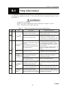
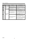
This section describes corrective actions to take if an alarm LED turns on.
The appropriate corrective action depends on the alarm code displayed. See Software User’s Guide
for information how to check the alarm log check and an example with displayed information.
In addition, LED display details are given in the following table:
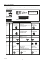
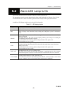
Table 5.2 LED display details
Display Description
PWR Lights in green when the device is powered on.
RDY
Blinks in green in the operation preparation state, and lights in green in the operation state.
Blinks in orange in the maintenance mode waiting state, and lights in yellow in maintenance
mode.
INDWN
No LED lights in normal state. Blinks in orange in the state of audio/video/network input
down or abnormal.
The alarm display by this LED can select lighting, blinking, and turning off excluding the
LED lighting by the temperature anomaly.
For more details of the alarm log and the setting method of LED, please refer
“IP-9610 Software User’s Guide.”
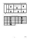
ALM
Alarm LED. Blinks or lights in orange when a device alarm occurs.
Lighting, blinking, and turning off can be selected by the setting about a part of the alarm
display by this LED.
For more details of the alarm log and the setting method of LED, please refer
“IP-9610 Software User’s Guide.”
LINK / ACT
Operation status LED of LAN, CONSOLE port.
This LED will be turned on when LINK of Ethernet is established and it will be blinked
when Ethernet packet is detected. It will be turned off when Ethernet cable isn’t connected.
10/100/1000M
Linked speed information of LAN, CONSOLE port.
This LED will be turned off when linked speed is 10BASE, it will be turned on when linked
speed is 100BASE, and it will be blinked when linked speed is 1000BASE.
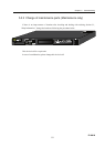
5.2