


C141-E134-01EN 8 - 3
8.3 Circuit Configuration
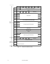
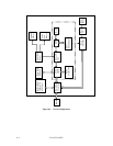
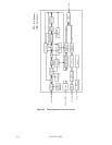
Figure 8.1 shows the circuit configuration of IDD.
(1) Read/write circuit
The read/write circuit consists of 2 high performance LSIs, Read Channel and Head Preamp,
which perform reading and writing data. 32/34 Modified Extended EPRML (MEEPRML) is
adopted as recording method, which realizes high density recording.
(2) Servo circuit
Voice coil motor position/speed control is carried out by a closed loop servo system and carries
out feedback control based on servo information recorded on the data surface. Analog servo data
is converted into a digital signal, and is then processed by a DSP. The digital signal is then
converted into an analog signal which then controls the voice coil motor.
The DSP accurately controls traffic positioning of each head using servo information on the data
surface.
(3) Spindle motor drive circuit
The spindle motor drive circuit drives the spindle motor. A drive current in the motor coil
generates a counter-electromotive voltage. The frequency of the counter-electromotive voltage is
compared, by the DSP, with a reference frequency derived by dividing the oscillator frequency.
The DSP uses the result of the comparison to control the rotational frequency of the spindle motor.
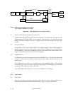
(4) Controller circuit
• The controller circuit has the following main functions:
• Data buffering (8 Mbyte, 4 to 32 segments)
• SCSI protocol control and data transfer control
• Sector format control
• ECC
• Error recovery and self-diagnosis