


C141-E134-01EN4 - 22
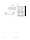
4.3.4 External operator panel (MP model)
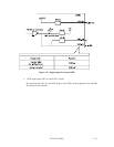
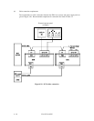
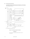
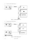
A recommended circuit of the external operator panel is shown in Figure 4.23. Since the external
operator panel is not provided as an option, this panel must be fabricated at the user site referring
to the recommendation if necessary.
(IDD)
CN1
S3
A1
A3
A5
A7
A10
-ID0
-ID1
-ID2
-ID3
GND
ID0
ID1
ID2
ID3
S3
A8
A11
-LED
+5V
(LED)
R
Approx. 300Ω
(*1)
CN2
S4
21
22
LED (+5V)
-LED
(LED)
(for 16-bit SCSI)
(*1) For connecting the external LED to CN2.
Figure 4.23 External operator panel circuit example
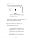
IMPORTANT
Do not connect the external LED to both CN1 and CN2. Connect it
to either of them.