


C141-E134-01EN xiii
FIGURES
page
Figure
1.1 MC model outer view...........................................................................................................1-5
Figure 1.2 MP model outer view...........................................................................................................1-6
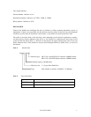
Figure 1.3 Disk/head configuration.......................................................................................................1-7
Figure 1.4 System configuration............................................................................................................1-8
Figure 3.1 Cylinder configuration .........................................................................................................3-2
Figure 3.2 Spare area in cell..................................................................................................................3-5
Figure 3.3 Alternate cylinder.................................................................................................................3-5
Figure 3.4 Track format.........................................................................................................................3-6
Figure 3.5 Track skew/cylinder skew....................................................................................................3-7
Figure 3.6 Sector format........................................................................................................................3-8
Figure 3.7 Alternate block allocation by FORMAT UNIT command.................................................3-13
Figure 3.8 Alternate block allocation by REASSIGN BLOCKS command........................................3-14
Figure 4.1 External dimensions (MC model) ........................................................................................4-2
Figure 4.2 External dimensions (MP model).........................................................................................4-3
Figure 4.3 IDD orientations...................................................................................................................4-4
Figure 4.4 Mounting frame structure.....................................................................................................4-5
Figure 4.5 Limitation of side-mounting.................................................................................................4-5
Figure 4.6 Surface temperature measurement points.............................................................................4-6
Figure 4.7 Service clearance area..........................................................................................................4-7
Figure 4.8 Current waveform (+12 VDC) .............................................................................................4-8
Figure 4.9 Power on/off sequence (1)....................................................................................................4-9
Figure 4.10 Power on/off sequence (2)....................................................................................................4-9
Figure 4.11 Power on/off sequence (3)....................................................................................................4-9
Figure 4.12 AC noise filter (recommended)..........................................................................................4-10
Figure 4.13 Connectors and terminals location (MP model).................................................................4-11
Figure 4.14 16-bit SCSI interface connector.........................................................................................4-12
Figure 4.15 Power supply connector (16-bit SCSI model)....................................................................4-12
Figure 4.16 External operator panel connector (CN1) ..........................................................................4-13
Figure 4.17 External operator panel connector (CN2) ..........................................................................4-14
Figure 4.18 16-bit SCSI ID external input.............................................................................................4-15
Figure 4.19 Output signal for external LED..........................................................................................4-17
Figure 4.20 SCSI cables connection......................................................................................................4-18