


xiv C141-E134-01EN
Figure 4.21 Connectors location of MC model .....................................................................................4-19
Figure 4.22 SCA2 type SCSI connector................................................................................................4-20
Figure 4.23 External operator panel circuit example.............................................................................4-22
Figure 5.1 SCSI bus connections (1 of 2)..............................................................................................5-4
Figure 5.1 SCSI bus connections (2 of 2)..............................................................................................5-4
Figure 5.2 IDD setting terminals position (MP model only).................................................................5-5
Figure 5.3 Setting terminator (CN2 on MP model only).......................................................................5-6
Figure 5.4 Checking the SCSI connection (A) ....................................................................................5-14
Figure 5.5 Checking the SCSI connection (B).....................................................................................5-15
Figure 6.1 Revision label.......................................................................................................................6-9
Figure 6.2 Indicating revision numbers...............................................................................................6-10
Figure 6.3 Test flowchart ....................................................................................................................6-11
Figure 7.1 Format of extended sense data .............................................................................................7-2
Figure 8.1 Circuit configuration............................................................................................................8-4
Figure 8.2 IDD operation sequence at power-on...................................................................................8-5
Figure 8.3 Block diagram of read-write circuit .....................................................................................8-8
Figure 8.4 Block diagram of servo control circuit...............................................................................8-10
Figure 8.5 Position of servo track........................................................................................................8-12
Figure 8.6 Servo frame........................................................................................................................8-12
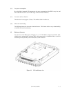
Figure A.1 Locations of connector (MC model) ...................................................................................A-2
Figure A.2 Locations of connectors and setting terminals (MP model) ................................................A-3