


C141-E134-01EN 8 - 7
8.6 Read/Write Circuit
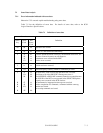
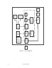
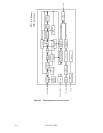
The write/read circuit consists of a head IC unit (in DE), write circuit, read circuit, and interface
circuit. Figure 8.3 is a block diagram of the read/write circuit.
8.6.1 Head IC
The head IC is mounted inside the DE. The head IC has a preamplifier and a write current driver,
and has a write error detection function. Each channel is connected to each data head, and is
switched by a serial port. If a write error, such as a head short-circuit or head disconnection is
detected, an error signal (WUS) is generated.
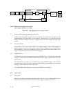
8.6.2 Write circuit
The write data is converted into the NRZ data (WDT by SCSI controller), and is sent, together
with the Write clock (WCLK) signal, to the write circuit. The NRZ data is converted into 32/34
RLL code by the encoder circuit, and is written to the disk.