


C141-E134-01EN3 - 10
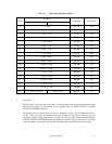
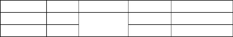
Table 3.4 Format capacity
Model Data heads Data block length User blocks Format capacity (GB)
MAM3367 series 8 71,770,616 36.74
MAM3184 series 4
512
35,885,344 18.37
Note:
Total number of spare sectors is calculated by adding the number of spare sectors in each
primary cylinder and the number of sectors in the alternate cylinders.
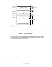
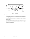
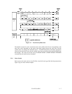
3.2 Logical Data Block Addressing
Independently of the physical structure of the disk drive, the IDD adopts the logical data block
addressing as a data access method on the disk medium. The IDD relates a logical data block
address to each physical sector at formatting. Data on the disk medium is accessed in logical data
block units. The INIT specifies the data to be accessed using the logical data block address of that
data.
The logical data block addressing is a function whereby individual data blocks are given addresses
of serial binaries in each drive.
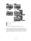
(1) Block address of user space
The logical data block address number is consecutively assigned to all of the data blocks in the
user space starting with 0 to the first data block.
The IDD treats sector 0, track 0, cylinder 0 as the first logical data block. The data block is
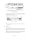
allocated in ascending order of addresses in the following sequence (refer to Figure 3.5):
1) Logical data blocks are assigned in ascending order of sector number in the same track.
2) Subsequent logical data blocks are assigned to sectors in every track except the last track in
ascending order of track number in the same cylinder. Within the same track, logical data
blocks are assigned in the same way as step 1).
3) Subsequent logical data blocks are assigned to sectors in every track except the last track in
ascending order of track number in the same cell. Within the same track, logical data blocks
are assigned in the same way as step 1).
4) For the last track in the same cell, subsequent logical data blocks are assigned to sectors other
than spare sectors in ascending order of sector number.
5) After blocks have been assigned in the same cell according to steps 1) to 4), subsequent logical
data blocks are assigned in ascending order of cell number in the same way as in steps 1) to 4).
Logical data blocks are assigned starting from track 0 in the next cell until the last cylinder
(immediately preceding the alternate cylinder n-1 shown in Figure 3.1) of the zone except
alternate cylinders in cells in the user space.