C141-E134-01EN 8 - 5
8.4 Power-On Sequence
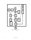
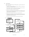
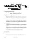
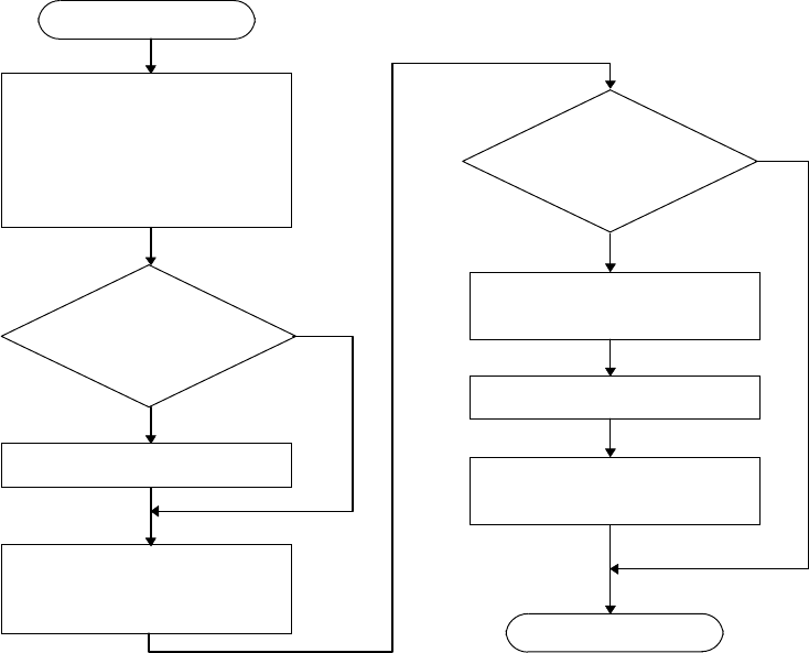
Figure 8.2 shows the operation sequence of the IDD at power-on. The processes shown in this
figure are explained below:
1) After the power is turned on, the IDD executes self-diagnosis 1 (MPU bus test, internal register
write/read test, and work RAM write/read test).
2) When self-diagnosis 1 terminates successfully, the IDD activates the spindle motor when the
motor start mode is set (SW1 is on; default setting at factory shipment).
3) The IDD executes self-diagnosis 2 (data buffer write/read test).
4) The IDD receives the START UNIT command, then the IDD activates the spindle motor when
the motor start mode is set. When the motor start mode is not set, the IDD terminates this
sequence and enters the command waiting state.
5) The IDD checks that the spindle motor rotation reaches a steady rotational speed.
6) The IDD executes self-configuration. This includes execution of the factory calibration which
is described on the next page and the processing of reading the format information and defect
position information written in the system zone.
7) The disk drive is in ready state and commands from the host system can be executed.
Motor start mode
switch setting
ON
OFF
(7)
(6)
(5)
(4)
ON
OFF
(3)
(2)
(1)
Power-on
Self-diagnosis 1
• MPU bus test
• Internal register
write/read test
• Work RAM write/read
test
Start
Activate spindle motor
Self-diagnosis 2
• Data buffer write/read
test
Motor start mode
switch setting
Check spindle motor
steady state rotation
Execute self-calibration
Drive ready state
(command waiting state)
End
Figure 8.2 IDD operation sequence at power-on


