


C141-E134-01EN3 - 8
SCT
PAD
SM1
PLO
SyncG1
SCT
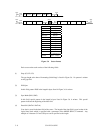
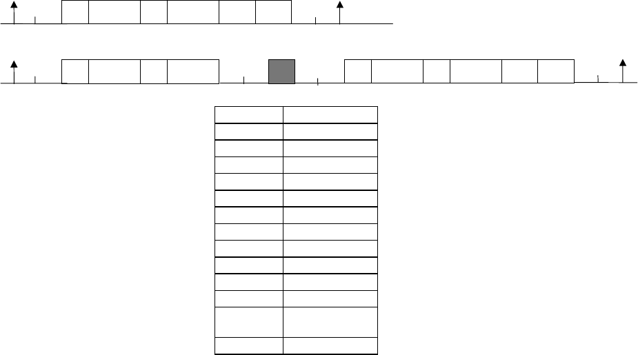
G1 6 bytes
G2 12 bytes
G3 8 bytes
PLO Sync 36 bytes
SM1 4 bytes
SM2 2 bytes
BCRC 4 bytes
ECC 60 bytes
PAD 6 bytes
DATA1 24 bytes
DATA2 488 bytes
DATA3
n bytes (0
≤
n
≤
464,
n is a multiple of 4.)
DATA4 (464 – n) bytes
G2
DATA1
SM2 BCRCDATA2 ECC
SCT
PAD
SM1
PLO
Sync
G1
SCT
G3
DATA1
SM2 DATA3
PAD
G2
SM1
PLO
SyncG1
DATA1 SM2 DATA4
Servo
BCRC ECC
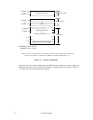
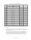
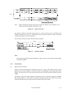
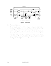
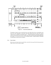
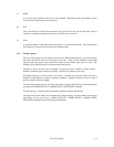
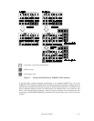
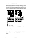
Figure 3.6 Sector format
Each sector on the track consists of the following fields:
(1) Gaps (G1, G2, G3)
The gap length at the time of formatting (initializing) is listed in Figure 3.6. No pattern is written
on the gap field.
(2) PLO Sync
In this field, pattern X'00' in the length in bytes listed in Figure 3.6 is written.
(3) Sync Mark (SM1, SM2)
In this field, special pattern in the length in bytes listed in Figure 3.6 is written. This special
pattern indicates the beginning of the data field.
(4) Data field (DATA1-DATA4)
User data is stored in the data field of the sector. The length of the data field is equal to that of the
logical data block which is specified with a parameter in the MODE SELECT command. Any
multiple of 4 between 512 and 528 bytes can be specified as the length.