


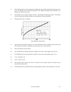
C141-E134-01EN 1 - 7
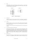
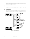
(2) Heads
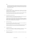
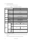
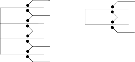
The MR (Magnet - Resistive) of the CSS (contact start/stop) type heads are in contact with the
disks when the disks are not rotating, and automatically float when the rotation is started. Figure
1.3 shows the configuration of disks and heads
Figure 1.3 Disk/head configuration
(3) Spindle motor
The disks are rotated by a direct-drive hall-less DC motor. The motor speed is controlled by a
feedback circuit using the counter electromotive current to precisely maintain the specified speed.
(4) Actuator
The actuator, which uses a rotary voice coil motor (VCM), consumes little power and generates
little heat. The heads at the end of the actuator arm is controlled and positioned via feedback of
servo information in the data.
The heads are positioned on the CCS zone over the disk when the power is off or the spindle motor
is stopped.
(5) Air circulation (recirculation filter, breather filter)
The disk enclosure (DE) configures a sealed room to keep out dust and other pollutants. The DE
has a closed-loop air recirculation system. Using the movement of the rotating disks, air is
continuously cycled through a filter. This filter will trap any dust generated inside the enclosure
and keep the air inside the DE contaminant free. To prevent negative pressure in the vicinity of the
spindle when the disks begin rotating, a breather filter is attached. The breather filter also
equalizes the internal air pressure with the atmospheric pressure due to surrounding temperature
changes.
(6) Read/write circuit
The read/write circuit utilizes a read channel mounted with a head IC that supports high-speed
transmission and an MEEPR4ML (Modified Enhanced Extended Partial Response Class 4
0
1
2
3
4
5
6
7
MAM3367
0
1
2
3
MAM3184